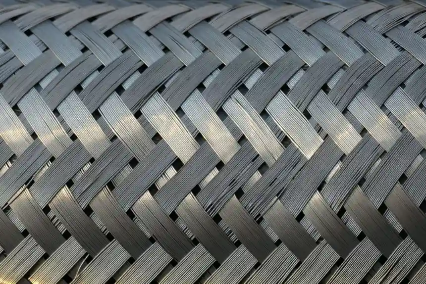
Mesh pads and vane packs solve the same problem (entrained liquid in a vapor stream) through different mechanisms, and picking the wrong one for a steam separator produces liquid carryover, re-entrainment, or premature flooding within one operating cycle.
Mesh pads capture droplets by impaction on a deep bed of knitted wire filaments, while vane packs separate by forcing the gas through a zig-zag path so droplets strike rigid corrugated plates. The two technologies overlap around 8-15 µm, but their operating envelopes differ enough that most operating envelopes pick a clear winner [S1][S2].
Cut Point, Velocity, and the Souders-Brown K-Factor
Knitted wire mesh demisters typically specify a Souders-Brown K-factor of 0.35 ft/sec (≈0.107 m/s) for vertical vapor flow and 0.42 ft/sec (≈0.128 m/s) for horizontal flow, in an air-water system at ambient conditions; these values are derated for elevated pressure and density [S1]. Standard non-pocketed vane packs run K ≈ 0.152 m/s, while double-pocket (DP) vane packs run K ≈ 0.259 m/s, a 70% capacity increase that is the defining reason to pay for a pocketed design on high-velocity service [S3].
Mesh pads are routinely rated to capture droplets as small as 1-3 µm when supplied as a high-density knit (B-GON®-type products reach 99% efficiency at 1 µm), and they are the default in clean, low-velocity vapor such as sulfuric acid towers, chlor-alkali absorbers, and refinery knockout drums [S2]. Vane packs cut at 8-15 µm, sized by plate spacing (15 mm pushes the cut to 8-10 µm, 30 mm captures only 15+ µm), and they tolerate gas velocities up to 6.5 m/s, roughly 60% above a standard wire mesh, which makes them the only defensible option for FGD scrubbers, compressor suction drums, and offshore separators [S3].
Fouling, Pressure Drop, and Failure Modes
Vane units are less susceptible to plugging and deterioration than mesh pads because their open channel geometry (12-30 mm plate spacing) lets solids pass, while a fouled mesh pad traps solids until the liquid-filled zone reaches the vapor inlet face and the pad floods [S6][S1]. Vane packs also run lower pressure drop per unit separation work: typical ΔP is 50-200 Pa across a vane bank, versus a mesh pad in a comparable clean service, and dense mesh pads reach higher pressure drops at the same velocity [S1][S3].
The failure signatures look similar but the remediation differs. A mesh pad that floods presents as sudden carryover with rising ΔP and the fix is clean or replace; a vane pack that re-entrains at high velocity presents the same way and the fix is to derate gas velocity, not to clean the plates. FGD service forces a water wash at 3-5 bar for 10-15 minutes per shift, otherwise calcium sulfate scaling bridges the plate gaps in 2-4 weeks and the unit has to come offline for manual cleaning [S3]. In high-fouling natural gas, no mesh or vane alone is enough: a cyclonic spin-tube pre-separator is installed upstream to drop the bulk liquid and solids, with the mesh or vane as a polishing second stage [S5].
Liquid Loading, Footprint, and Two-Stage Stacks

Mesh pads handle moderate liquid loads in clean service; vane packs handle heavy liquid loads and slugs because the open channels do not flood the way a deep knit does [S6][S5]. Selection on liquid loading alone follows a simple rule: <10 bbl/MMSCF routes to a scrubber with mesh, >10 bbl/MMSCF or expected slugs route to a two-phase separator with vane or cyclonic internals [S5]. Footprint also diverges: vane packs are physically larger than mesh pads for the same duty, so a tight plot favors mesh, while a green-field column with room for internals favors vane for the velocity headroom [S2].
When neither device alone is the right answer, stack them: a mesh pad as first stage to coalesce fine mist into larger droplets, then a vane pack as second stage to knock out the larger droplets at high capacity. This arrangement is standard practice for variable-inlet scrubbers and is documented as a legitimate hybrid rather than a redundant design [S5]. For comparison with material-side constraints, 316L vs 317L stainless pitting resistance matters when the steam carries chlorides that attack standard 316 internals.
Materials, Standards, and Spec Discipline
Mesh pad materials span stainless steel, polypropylene, PVDF, ETFE, and PFA, with the polymer choices driven by corrosion rather than temperature; vane plates are supplied in similar alloys and fiberglass-reinforced plastic for FGD [S2][S3]. Mesh pads are sized by wire diameter, surface area, mesh thickness, and the interfacial surface tension between the fiber and the collected liquid, four variables that must be specified, not assumed [S5]. Vane pack selection must lock plate spacing, pocketed vs non-pocketed geometry, and K-factor in writing, because the spacing choice alone shifts the cut point by 5-7 µm and cannot be field-corrected [S3].
Capacity factors are reported in ft/sec (mesh) and m/s (vane), so any spec that mixes units without converting will be wrong by a factor of 3.28; vendor data sheets quoting both mesh K-factors and vane K-factors in the same project must be normalized to one system before hydraulic checks [S1][S3]. Material selection for chloride-bearing steam is covered separately in 304H vs 304L high-temperature pressure vessel spec decisions, where the same alloy trade-off shows up in separator shell and internal metallurgy.
Selection Matrix and Decision Rule
Use mesh pad when droplets are ≥3 µm, gas velocity is below ~1.0 m/s, fouling is absent, and pressure drop must be minimized; use vane pack when gas velocity is 1.0-6.5 m/s, droplets are >20 µm, fouling or solids are present, or turndown is needed (Souders-Brown K = 0.152 m/s standard, 0.259 m/s pocketed) [S1][S2][S3]. Use a two-stage mesh-then-vane stack when the inlet droplet distribution is broad (1-100 µm) and the service is variable, and add a cyclonic pre-separator when solids content would otherwise blind the mesh within days [S5].
Track two signals on every new separator spec: the calculated operating velocity as a fraction of the Souders-Brown K-factor (mesh should run at 70-85% of K, vane at 60-80% of K for clean service, lower for fouling), and the predicted ΔP at design flow, which for vane packs should land in the 50-200 Pa band rather than the upper end [S1][S3]. For related alloy and process hardware trade-offs, see 304 vs 316 stainless scrap pricing as a sanity check on whether the specified mesh alloy still pencils out at current scrap-driven surcharges.
The underlying component specifications are covered under cyclone separator, and steam trap.