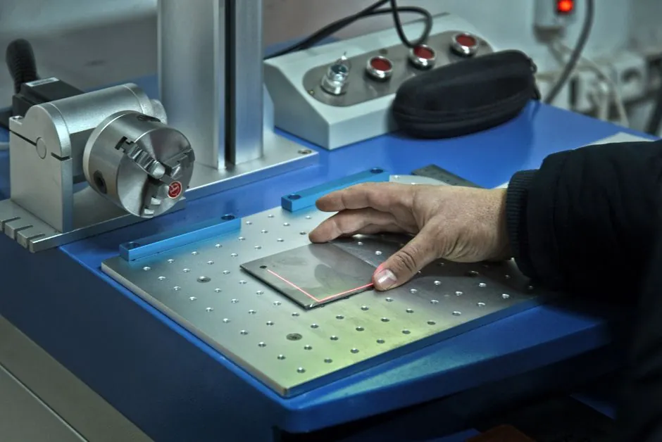
Selection of a surface roughness tester is governed by four engineering numbers: the Ra working range of the parts being inspected, the required cutoff (sampling) length, the evaluation/traverse length, and the geometry access around the feature being measured. Mis-sizing any one of these produces a number that looks valid on the display but is not comparable to a drawing callout [S1][S3].
For the great majority of machined metal components Ra is the parameter of record, with Rz and Rt used to expose extreme peaks that Ra averages away. Contact stylus instruments remain the workhorse because they are direct, traceable, and read absolute displacement in micrometres; non-contact optical and interferometric systems enter when the part is soft, reflective, micro-featured, or geometrically inaccessible to a 2 µm tip radius stylus [S1][S3][S5].
Ra Working Range and Where Each Tester Class Fits
Most general-machining drawings sit between Ra 0.4 µm and Ra 6.3 µm, a band that a portable skidded stylus instrument with a 0.001 µm resolution display covers directly [S2]. Honed cylinder liners and ground bearing journals target the Ra 0.1–0.4 µm band and demand a skid-less pickup plus a short cutoff of 0.08 mm, so that surface micro-defects are not averaged out by the filter [S2].
Optical and white-light interferometric systems are the only practical option below Ra 0.05 µm, on polished mould cavities, optical-grade glass, and semiconductor wafers, because stylus contact itself disturbs the very features being measured [S3][S5]. Optical systems are also faster over area scans but require a specular or controlled-reflectance surface; matte, oily, or transparent parts can defeat them [S3].
Cutoff, Evaluation Length, and Filter Settings
A roughness reading is meaningless unless the cutoff (λc) and evaluation length are matched to the texture being measured. ISO 4288/1996 and ASME B46.1 define a lookup table that ties λc to the expected Ra band; the practical consequence is that a 0.8 mm cutoff used on a finely lapped surface will hide the waviness, while a 2.5 mm cutoff on a turned surface will integrate the feed marks and understate Ra [S1][S3].
Evaluation length is normally 5 cutoffs concatenated, which for a 0.8 mm cutoff gives a 4 mm trace, the minimum credible length for a stable average. Engineers should refuse any single-cutoff single-trace report on a production drawing, because a single 0.8 mm trace over a turned surface can swing 30-50% between passes; the multi-cutoff mean is the only number worth signing off [S1][S3].
Contact vs Non-Contact: Decision Criteria

Four criteria separate the two families: surface hardness, feature size, required 2D vs 3D output, and shop-floor vs lab environment. Contact stylus systems handle hardened steel, cast iron, and most bearing surfaces, produce 2D profiles that map to Ra/Rz/Rt directly, and survive shop vibration with a 2 µm tip radius; their weakness is micro-features narrower than the stylus tip and soft or coated parts that the diamond will scratch [S1][S3][S4].
They lose out on oily, transparent, or mirror-finish-but-curved parts, and on any shop environment where ambient light or vibration cannot be controlled [S3][S5]. For most general metalworking, a contact stylus remains the default; optical is specified when the part is soft, the feature is sub-stylus, or a 3D map is required for coating-adhesion or wear-prediction modelling [S1][S3].
Stylus Geometry, Skidded vs Skid-less, and Access
The 2 µm tip radius, 90° cone, and ~0.8 mN static force are the de-facto contact standards for general metrology; small-hole, deep-groove, and concave-radius styli extend the same instrument to internal bores, O-ring grooves, and bearing raceways [S4]. Skidded pickups integrate a skid that rides on the surface as a mechanical low-pass reference, which is why they are cheaper and more forgiving on the shop floor but cannot resolve low-frequency waviness or measure below roughly Ra 0.1 µm [S2].
Skid-less pickups use an internal reference datum, so the full unfiltered profile is available for Rk/Rvk (Bearing Area Curve) analysis on sealing and lubrication surfaces, and the usable range extends to sub-µm Ra. For complex-geometry parts such as turbine blades, gear tooth flanks, and threaded roots, a skid-less pickup on a split-probe or remote-detector drive is the only credible answer; the Mitutoyo SJ-210/SJ-310 family and the QualiSurf III-Plus class are typical shop-floor and lab pairings [S2][S4].
Traverse, Stand, and Sample-Handling Hardware
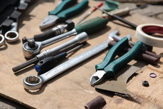
Traverse length sets the maximum evaluation length. Portable units typically offer 4-25 mm traverses, enough for Ra/Rz at standard cutoffs; CNC or lab instruments add 50-200 mm traverses for long traces, statistical sampling, and form error separation. A manual column stand with 250 mm vertical travel is the minimum credible support for a shop-floor handheld drive on flat or prismatic parts, because hand-traversing introduces velocity errors that the instrument cannot correct [S4].
For small or thin components, a height-gage adapter or magnetic stand adapter mounts the drive to existing metrology fixtures, which removes the operator-induced skew that otherwise dominates the measurement uncertainty budget. Reference specimens are not optional: an Ra 3.00 µm (119 µin) block verified daily is the only way to catch stylus wear before it shows up as a low Ra on a part that has not changed [S4].
Calibration, Standards, and Audit Trail
Two standards govern almost every commercial drawing: ISO 4287/1997 for the parameter definitions (Ra, Rz, Rt, Rp, Rv) and ISO 4288/1996 (mirrored by ASME B46.1) for the sampling rules that map an unknown surface to the right cutoff. Traceability runs through a calibrated reference specimen, typically Ra 3.00 µm, with the daily verification logged against stylus wear and pickup drift; without this loop, a metrology lab cannot defend a pass/fail decision on a critical aerospace or medical surface [S1][S2][S3].
A second layer is application-specific. Medical implants and food-processing surfaces often call out the Rk family (Rk, Rpk, Rvk) to characterise the bearing area curve, which predicts how well the surface retains lubricant or resists bacterial colonisation. The plain Ra number is not enough on these drawings, and the chosen tester must compute Rk in firmware, not as a manual post-process [S2][S3].
Where the Mainstream Choice Is the Wrong Choice
A portable skidded stylus unit is the wrong pick in three common cases: (1) any surface that must be measured below Ra 0.1 µm, where the skid itself filters out the signal; (2) any soft polymer, elastomer, or coated part where a 0.8 mN stylus will permanently mark the surface, as in linear guide slideway inspection where the coating thickness is comparable to the stylus load footprint; (3) any feature narrower than roughly 5 µm, where the 2 µm tip radius convolves the geometry into the profile [S1][S3][S4]. In all three, a skid-less contact pickup or an optical profiler is the right tool even at three to ten times the price.
Conversely, an optical profiler is the wrong pick on a dirty shop floor, on oily as-machined parts without a clean-room rinse, or on a curved mirror-finish where the focal plane walks off the working distance. Buyers chasing a single instrument for every job consistently underperform two specialised instruments; the audit-winning configuration is a portable skidded stylus for 80% of throughput, paired with a lab skid-less or optical station for the 20% that drives the real warranty risk [S1][S2][S3].
Selection Shortlist Logic
Shortlist by answering four questions in order. First, what is the expected Ra band and is Rk required; this fixes whether a portable Ra-only unit is enough or a full-parameter lab instrument is needed. Second, what is the cutoff per the ISO 4288 lookup; this fixes the minimum evaluation length and hence the traverse. Third, is the part accessible to a 2 µm stylus at 0.8 mN, and is the geometry inside-bore, curved, or thread-root; this fixes skid-less vs skidded and stylus type. Fourth, is the environment a shop floor with vibration and chips, or a temperature-controlled lab; this fixes the housing, stand, and reference-specimen discipline [S1][S2][S4].
For shop-floor work in the Ra 0.4-6.3 µm band on flat or prismatic machined parts, a portable stylus such as the Mitutoyo SJ-210 with a manual column stand and a daily Ra 3.00 µm reference block is the default shortlist. For Ra below 0.1 µm, Rk-bearing-area work, or sub-millimetre features, escalate to a skid-less lab instrument or an optical/interferometric system, and budget for vibration isolation and reference specimens at multiple Ra levels. Buying below the cutoff requirement is the single most common procurement error, and it shows up as warranty returns six to twelve months after the line is signed off [S2][S3][S4].
Two trackable signals to watch over the next quarter: any update to ISO 21920 (the 2021 successor to ISO 4287/4288 that consolidates areal parameters), and the price trajectory of sub-µm optical probes, which has been the gating factor for medium-tier shops adopting 3D area-scanning instead of 2D traces. Either change shifts the cost line enough to revisit a shortlist that was correct in 2024 but is no longer optimal in 2026 [S2][S3].
For component-level specifications, see crossed roller guide.
See also our earlier report, Choosing an Optical Comparator for Water Treatment QA.