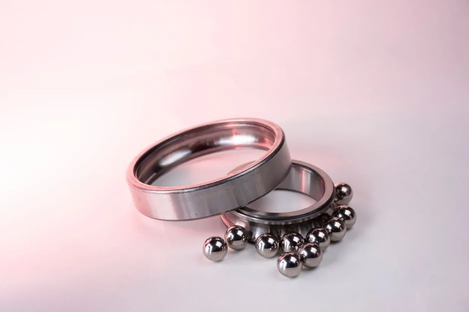
A tandem angular contact bearing arrangement places two or more single-row angular contact bearings in line so their contact-angle lines run parallel, splitting a heavy unidirectional axial load across the stack while still carrying radial load through the same row [S1][S2][S6].
This is the configuration to pick when the shaft sees thrust in one direction only and the load is too high for a single bearing. When thrust reverses, a duplex (DB or DF) pair takes over [S5][S6]. For background on the basic part type, the angular contact bearing reference entry walks through contact angle and load lines.
Why a tandem pair, and what changes in the load path
In a single-row angular contact bearing, the line joining the ball-to-raceway contact points is set at an angle to the bearing axis, typically 15°, 25°, 30°, or 40°, and that line is what carries the axial component of the load [S1][S3]. One row alone can only thrust in the direction its contact angle is opened toward; a second row mounted in the same direction stacks the capacity [S2][S5].
Schaeffler's single-row product documentation states the contact lines run parallel to each other in a tandem arrangement, and that the axial force is distributed equally over both bearings, with the limitation that thrust can only be absorbed from one direction [S6]. The NSK angular contact ball bearings product page reinforces that the geometry sustains significant axial load in one direction at the same time as radial load [S3]. Tameson's 2022 bearing guide (2022-02) summarises the same rule: a tandem mount accommodates single-direction axial loads plus radial loads, and both bearings receive equal share of the axial force [S8].
Tandem vs back-to-back (DB) vs face-to-face (DF): a four-criterion comparison
The three pairing geometries differ on four decision criteria: thrust direction, moment capacity, misalignment tolerance, and effective load line spread. [S5]
On thrust direction, tandem supports axial load from one direction only, while DB and DF each support axial load from either direction with one bearing carrying each direction [S1][S2][S6]. On moment capacity, DB gives the widest spread between the two load lines, which gives the highest resistance to tilting moment, whereas tandem shares one effective load line and therefore resists moment poorly [S1][S5]. On misalignment tolerance, DF allows the most because the apexes of the contact angles point toward each other; DB is the most rigid and the least tolerant of misalignment [S1]. On radial load handling, all three configurations handle radial load through the same single-row geometry [S1][S3]. The relevant thrust bearing comparison pages make the same point in plain terms: pure thrust bearings have no radial capacity, so when radial is also present, an angular contact geometry is the right tool.
When tandem is the right pick, and when it is wrong
Tandem is correct when the application has a heavy, steady, single-direction axial load combined with radial load: screw drives with a defined thrust direction, helical gear pinions where the gear mesh force is one-directional, pumps with a defined impeller thrust, and machine-tool spindles carrying a unidirectional cutter force [S1][S3][S5]. A common form-factor is the universal-matched single row (for example 7200 BECBP), which the manufacturer data shows used in compressors, screw chillers, industrial pumps, elevator hoists, and electric motors [S1].
Tandem is wrong when the load can reverse. Mounting a tandem pair against reversing thrust will over-load one bearing and lift the other, so a DB or DF duplex, or a double-row angular contact, is specified instead [S2][S5]. The ScienceDirect overview is direct on this: tandem mounting is used for heavy unidirectional thrust loads, and duplex mounting (face-to-face or back-to-back) is used for two-directional thrust loading [S5]. Tandem is also wrong where moment load dominates, because the parallel contact lines give a near-zero moment arm; DB is the geometry for that case [S1].
Combined arrangements and stack sizing
Tandem does not have to be a two-bearing stack. NTN-SNR's Bearing Wizard notes that O, X, and tandem arrangements can all be combined with each other, so a TBT (tandem paired back-to-back with a third bearing facing the opposite direction) is a standard four-bearing layout for heavy thrust in both directions without losing the unidirectional thrust capacity of the tandem pair [S2][S4]. QIBR catalogues the same TBT pattern and lists single-row, double-row, and four-point contact variants in the same family tree [S4].
Stack depth is a design choice, not a fixed rule. Two bearings in tandem roughly double the single-row axial capacity; three or four in line scale further, bounded by speed, lubrication, and the additional frictional heat each row adds. The general OEM guidance is to keep the stack as short as the load requires, because every added row reduces the effective load line spread and adds heat [S1][S5]. For a process engineer picking a ball bearing family for a spindle, the rule of thumb is: one row if axial is light, two in tandem if axial is heavy and unidirectional, DB if axial reverses and moment is high, DF if axial reverses and some misalignment must be tolerated [S1][S5][S6].
Preload, contact angle, and operating limits

Because tandem bearings share thrust, preload specification is tighter than for a single row. The contact angle sets the axial-to-radial split: a 15° contact angle biases the bearing toward radial load with limited axial, and a 40° contact angle biases it toward axial load at the cost of radial capacity and a lower speed ceiling [S1][S3][S5]. ScienceDirect's reference states the contact angle does not usually exceed about 40° in angular contact ball bearings, and that the inner/outer raceway radius to ball diameter ratio sits in 0.52 to 0.54 [S5].
For matched pairs, manufacturers grind the end faces so the pair is preloaded when mounted against a second reference face; the preload class (light, medium, heavy) is selected for the duty. Misalignment on a tandem pair must be kept near zero, because the parallel contact lines amplify any angular error into uneven load share between the two rows [S1][S6]. For a deeper look at preload classes and how to read a manufacturer's suffix code, the roller bearing reference entry walks through the equivalent logic for cylindrical and tapered roller bearings, which use the same matched-pair language.
Material and lubrication notes specific to tandem stacks
Stacked rows multiply heat dissipation problems. A two-row tandem at the same speed and load runs hotter than a single row because two cages churn the oil, and a three-row stack runs hotter still. Standard through-hardened chromium steel (DIN 100Cr6 / AISI 52100) is the default for tandem stacks up to about 120°C continuous, with case-carburised variants used where shock load is present [S1][S3]. For higher speed or higher temperature, hybrid ceramic bearing stacks (silicon nitride balls, steel races) are common because the lower mass and lower friction of the ceramic balls offset the heat added by the second row.
Lubrication choice is dictated by the slowest row in the stack, which is the most heavily loaded row. Grease is standard for slow to moderate speeds with simple sealing; oil bath or oil-mist is used where heat rejection matters, which is most tandem applications because of the doubled heat input [S1][S3]. For applications where the bearing is one of several components in a larger machine spec, parts lists commonly cross to a linear bearing for the carriage side and to an angular contact stack for the thrust side, with lubrication and sealing treated as a single subsystem.
Common mistakes when specifying a tandem pair

Three errors come up repeatedly. First, specifying tandem where thrust reverses: the unloaded row lifts, the loaded row fatigues early, and the failure is misread as a lubrication problem [S2][S5]. Second, mixing contact angles between the two rows: a 15° row stacked with a 40° row shares thrust unevenly because the higher-angle row carries more axial per unit of deflection, and the lower-angle row never reaches its rated load [S1][S5]. Third, ignoring the moment load: a tandem pair has roughly the moment capacity of a single row because the contact lines are co-linear, so a shaft that tries to tilt the stack will deflect until one row is overloaded [S1][S6].
For a related comparison on how a different bearing type handles the same thrust problem, see the deep dive on stainless steel tapered roller bearings, which sets out the tapered-roller equivalent of the tandem rule. Engineers pairing a tandem stack with a gear or belt drive should also check the stainless shaft key sizes reference, because the keyway on the shaft dictates where the inner ring can be axially located and therefore the stack's effective spread.
Trackable signals: confirm that the duty cycle is single-direction thrust before ordering a tandem pair; verify the contact angle suffix (C, AC, B, E or the manufacturer's 15°/25°/30°/40° designation) on both rows is identical; size the stack for the worst-case combined radial plus axial load, and size the housing for the reduced moment capacity the stack actually has.