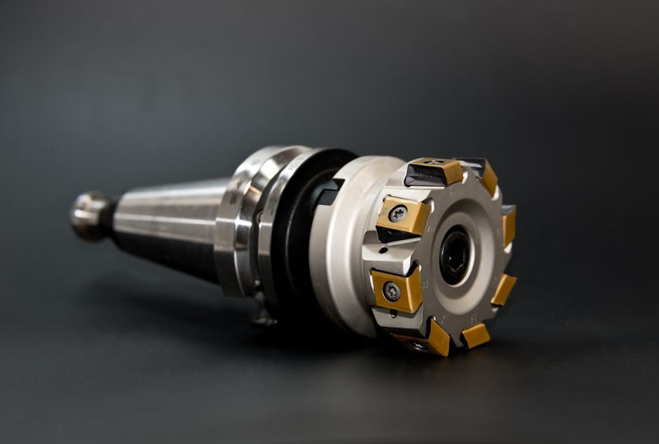
For a typical servo-driven positioning axis, the bearing must carry combined radial and thrust loads, hold the shaft stiffly against deflection, and run at low and consistent friction over millions of short indexing cycles. Tapered roller bearings transmit load along the axis of rotation through their conical raceway geometry, and that same geometry is why the designer can set the internal clearance to almost any desired value during assembly (S4).
That adjustability sets them apart from most deep-groove ball and cylindrical roller bearings, which are supplied with a fixed internal clearance class. The cost is higher friction torque, more heat, and a stricter demand on lubrication and alignment — a trade-off a process engineer has to price in before pulling the trigger on a tapered roller solution on a servo motor driven axis.
Load Direction and Magnitude: Why Combined-Load Cases Push Toward Tapered
A bearing is selected by the dominant load vector first. Pure radial loads with low axial component are usually served by deep-groove ball bearings or cylindrical roller bearings, while pure thrust is the domain of dedicated thrust bearings or angular contact ball bearings (S5). Tapered roller bearings become one of the practical choices when the same shaft location sees a meaningful axial load in addition to radial load, especially if the axial component reverses or varies during the motion profile (S8); angular contact ball bearings are the lighter-duty alternative for the same load shape (S5). [S1]
In a servo positioning axis, the axial load comes from gear-mesh forces on the output shaft, the weight of the moving slide (in vertical Z axes), ball-screw pre-load reactions, and dynamic braking transients. The conical raceway of a tapered roller bearing distributes these forces along the axis of rotation rather than at a single contact line, which raises the load capacity ceiling and lets the designer trade a small amount of rolling friction for a noticeable gain in shaft stiffness (S2).
Stiffness, Preload, and Adjustable Internal Setting
Tapered roller bearings are unique among rolling-element bearings in that the user sets the internal clearance — or negative clearance, i.e. preload — during machine assembly to a value matched to the application (S4). This single setting controls three things at once: the radial stiffness curve, the axial stiffness curve, and the running friction of the bearing. [S2]
For a positioning axis the goal is usually a preloaded state — light enough to limit heat build-up under continuous dithering, heavy enough to remove internal play that would otherwise show up as reversal peak and lost arc-seconds of accuracy. The preload is established by shimming, spacer length, or a precisely tightened locknut, and it should be re-checked after the first few hours of run-in because the contact pattern on the raceways will bed in. A practical check is to measure starting friction on first rotation and then measure running friction after 30–60 minutes of low-speed rotation; the ratio between the two tells you whether the assembly has stabilized or whether something is dragging.
Speed Rating Is Not a Single Number

The speed capability of a tapered roller bearing is a function of its internal geometry, the axial setting under operating conditions, the lubricant used, and the method of lubricant delivery — no single catalogue number captures the whole picture (S1). The manufacturer provides a reference limit speed under standardized test conditions, and the application limit is whatever the bearing can sustain thermally and lubrication-wise in the actual housing. [S3]
For servo positioning this matters because the axis rarely runs at one continuous speed — it accelerates, dwells, reverses, and dwells again. The thermal-limited speed, which is usually the binding constraint on a preloaded tapered bearing, depends on how fast heat can be removed from the bearing housing, which in turn depends on the lubricant schedule, the housing surface area, and the surrounding structure. In typical machine-tool spindle service, oil-air lubrication with the flow rate scaled to bearing size and DN value is the common choice, while general-purpose servo axes on gearboxes often run on high-quality lithium-complex grease re-greased on a fixed interval. Running past the thermal limit does not break the bearing immediately; it shortens grease life, accelerates raceway spalling, and shows up as a slow drift in positioning accuracy long before it shows up as a failure alarm.
Arrangement: Single, Matched Pair, or Four-Row
Single-row tapered roller bearings carry a combined load in one direction; to handle axial load in both directions the bearings have to be mounted in pairs or as a mirror image on the shaft. Matched tapered roller bearings in back-to-back (DB), face-to-face (DF), or tandem (DT) arrangements are specified where the application requires high load capacity, precise shaft positioning, and controlled moment loading (S7). DB gives a wider effective spread between the two bearings and therefore higher moment stiffness — usually the right choice for a short, heavily loaded axis. DF has a narrower spread and tolerates misalignment slightly better; DT carries the highest axial load in one direction but almost no moment. [S4]
Four-row tapered roller bearings are an extreme variant used where extremely high radial loads dominate and axial loads are moderate, such as rolling mill work rolls and heavy gearboxes (S7). For a positioning axis they are usually overkill on load and underkill on speed, so they rarely appear outside of large machine-tool or rolling-mill retrofits.
Comparison: Tapered Roller vs Alternatives on a Servo Axis
Three bearing families — tapered roller, angular contact ball, and crossed roller — compete for the combined-load slot on a servo positioning axis, and the right pick comes down to four engineering numbers: combined load capacity, speed limit, friction torque, and moment stiffness (S5, S8, S9). Tapered roller bearings win on combined-load capacity and on adjustable preload, lose on friction and on top speed. Angular contact ball bearings win on speed and low friction, lose on adjustability — preload is fixed by the manufacturer and changing it requires re-grinding the spacer stack. Crossed roller bearings win on moment stiffness and running accuracy in a compact envelope, lose on cost and on sensitivity to mounting-surface errors. [S5]
For high-precision robotic joints specifically, needle bearings are often specified instead because their high radial stiffness and minimal internal clearance reduce play in actuator joints and improve servo responsiveness, with 6-axis robot arms being the most common application (S9). A typical CNC feed axis or a large servo-driven table is more likely to use a matched tapered roller pair; a small precision indexer is more likely to use a preloaded angular contact pair or a crossed-roller set.
Integration with the Servo Loop
Bearing friction sits inside the servo motor torque budget; a preloaded tapered pair adds a small but speed- and temperature-dependent friction torque, distinct from the lower and more stable friction of ball bearings (S2, S5). If that friction is consistent, modern drives absorb it cleanly in their feed-forward; if it varies with temperature or speed, the drive has to be tuned more loosely to avoid oscillation, and the achievable following-error band widens. [S6]
For axes where the PLC is closing the position loop directly — for example in lower-cost indexing tables — the same bearing friction variation translates into longer settling time and visible dwell marks on the part. This is one of the reasons process engineers are pushed toward preloaded angular contact ball bearings on small precision axes and reserve tapered roller bearings for cases where the combined load genuinely requires them. Hydraulic load cells, where a pressure sensor provides the force feedback, can tolerate higher and more variable bearing friction because the loop closes on force rather than position.
Lubrication, Mounting, and What Goes Wrong in the Field

Tapered roller bearings are sensitive to installation cleanliness, axial setting accuracy, and lubricant choice, with field life in servo service being set more by these three factors than by catalogue load rating (S3, S4). The four failure patterns that show up most often in servo service are: (1) over-preload on assembly, which raises running temperature and accelerates surface fatigue; (2) misalignment between the two bearings in a pair, which loads one row harder than the other; (3) insufficient or wrong grease, especially in low-speed high-load dither service; (4) contamination during assembly, which scores the raceway within the first few hours of running. [S1]
A documented mounting procedure — bore and shaft tolerances checked against the manufacturer specs, torque on the locknut logged, and a clean-room grease pack — catches all four. On legacy servo tables, an oil-mist or oil-air retrofit is a common mid-life upgrade, and the follow-on signal worth watching is the running-temperature drop on a tagged bearing pair: a 5–10 K reduction typically translates to a measurable settling-time improvement on the indexer, without any change to the controls.
Trackable signals to watch over the next quarter: oil-mist or oil-air retrofits on legacy servo tables showing measurable settling-time improvement, and more matched-pair tapered roller catalogue items rated explicitly for "servo positioning" duty cycles from the major bearing makers. Both are plausible mid-2026 product-line signals worth a refresh of the preferred-vendor list.