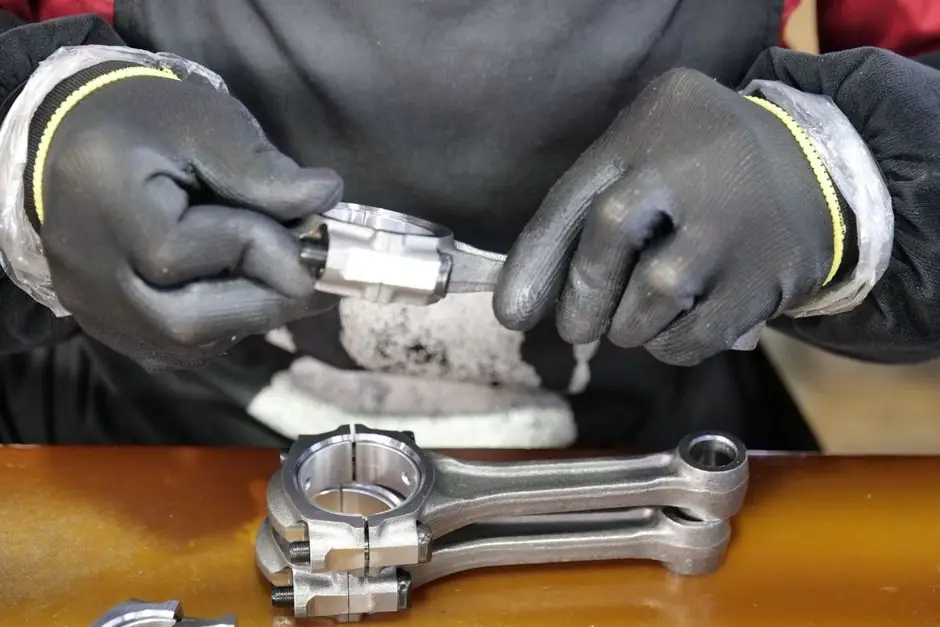
A torque sensor, also called a torque transducer or torque meter, is an in-line instrument that converts the twisting force on a rotating or static shaft into an electrical signal, with standard ranges spanning 0.1 N·m, 0.3 N·m, 1 N·m, 5 N·m, 10 N·m, 300 N·m, 1000 N·m and up to 10,000 N·m on commercial digital rotary units [S1][S4]. A dynamometer is a measurement system that resolves both torque and rotational speed to deliver mechanical power, and is built around a torque sensor plus a speed/angle pickup, a reaction frame, and often a brake or load absorber [S2].
The two overlap physically (a dynamometer always contains a torque-measuring element) but differ in scope: the torque sensor answers "how much twist", while the dynamometer answers "how much twist at what rpm, therefore how much power". Output options on current industrial torque sensors include strain-gauge bridge mV/V, ±5 V or ±10 V analog, 4–20 mA (or 4–12–20 mA three-state for direction), RS485, USB, and integrated frequency/square-wave speed pulses at 120 pulses per revolution [S3][S4].
Transduction Principles and Signal Outputs
Industrial torque sensors are dominated by bonded foil strain-gauge Wheatstone bridges on a deforming shaft, giving the unamplified mV/V output that is the de-facto standard for both reactive (non-rotating) and slip-ring rotary torque sensors [S3]. For higher-speed or maintenance-free service, contactless rotary torque sensors use the same strain-gauge element but transmit via inductive or capacitive coupling, adding an integrated amplifier so the output is ±5 V (default) or ±10 V (option), with RS485 or USB as digital alternatives [S3].
Piezoelectric and magnetostrictive principles exist for dynamic and high-bandwidth work, but the public product data on Lorenz Messtechnik, Transducer Techniques, and the ATO DYN-series focuses on strain-gauge implementations, with bridge output, ±5 V torque, RS485, and a 5 V square-wave speed signal at 120 pulses/rev as the documented options for rotary units in 2025–2026 [S1][S3][S4]. For a practical decision on a bench dynamometer, see the torque wrench tester reference for adjacent static-torque QA work.
Reactive vs Slip-Ring vs Contactless Rotary Designs
Reactive (non-rotating) torque sensors are wear-free, sit on the stationary side of the drivetrain, and are specified with explicit limit shear force and limit thrust load so that extraneous forces do not bias the strain-gauge element; optional extended-temperature builds run from -30 °C to 120 °C [S3]. Typical applications include extruder reaction torque, screwdriver testing, and bearing-friction torque determination [S3].
Slip-ring rotary torque sensors transmit the same mV/V bridge signal through low-wear slip rings, often with an integrated speed/angle channel, and are recommended for individual or random inspections at low rotational speed rather than continuous duty [S3]. Contactless rotary torque sensors replace the slip ring with inductive or capacitive power-and-data transfer, supply an amplified ±5 V / ±10 V or RS485/USB output, and split mechanically into bearing and bearingless types; the bearingless form eliminates bearing friction from the measurement chain and is therefore preferred for higher continuous speeds [S3]. For the broader test-bench context, the dynamometer reference covers how these elements assemble into a complete power-measurement system.
Range, Accuracy, and Directional Output
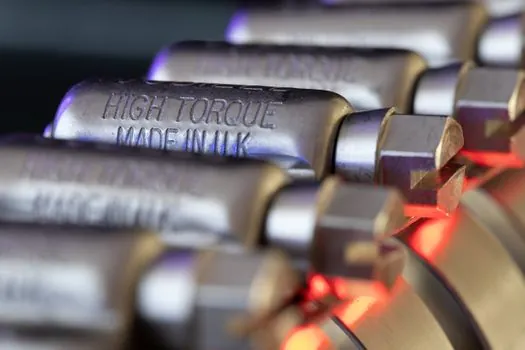
Range selection follows the rule of thumb "specify the next standard size above the maximum expected torque", visible in vendor guidance: a 25–30 N·m roller application was served by a 100 N·m sensor, a 10–400 N·m test request was answered with a 500 N·m model, and a 500 N·m actuator requirement at 4500 RPM was answered with a recommendation to step up to 800 N·m to keep the sensor in its linear range [S4]. Coaxiality of the through-shaft coupling is flagged in the same guidance as a hard requirement for in-line rotary installations [S4].
Bidirectional torque is handled differently by signal type: a ±5 V analog output natively represents forward and reverse torque, an RS485 stream can carry signed torque plus speed, while a current loop can indicate direction by a three-state 4–12–20 mA pattern (4 mA = reverse, 12 mA = zero, 20 mA = forward) where the sensor supports that mode [S4]. Square-wave speed output is documented at 5 V amplitude, 120 pulses per revolution, sufficient to feed an external counter or PLC high-speed input [S4]. Calibration against a reference standard is repeatedly called out as the way to keep the linear mV/V-to-N·m relationship trustworthy over the sensor's full range [S1].
Dynamometer Use Cases: Engine, Motor, and Biomechanics
An engine or motor dynamometer is, in spec terms, a torque sensor plus a speed pickup plus a load absorber (eddy-current brake, hysteresis brake, generator, or calibrated pump) and a frame that reacts torque to ground. A 2026 application example on the ATO rotary torque sensor thread specifies exactly that role: an actuator dynamometer, maximum output torque 500 N·m, maximum shaft speed 4500 RPM (471 rad/s), maximum output speed 5.8 rad/s, with the torque sensor chosen in the 800 N·m range for headroom [S4].
A second, very different dynamometer class is the clinical/biomechanical unit, where the same torque-plus-speed principle is applied to a human joint. The MyoWrist dynamometer measured isometric wrist flexion and extension in 345 healthy subjects aged 5–80 and in 9 LGMD2C patients, with intra-rater and inter-rater ICC above 0.9, a small learning effect of about 4% higher on retest, sensitivity down to 0.82 N·m, and patient strength quantified at 39 ± 17% of predicted normal values [S2]. For QA on the static side of the same family, the torque sensor reference details how the underlying transducer is graded when not used as a power meter.
Decision Matrix: Torque Sensor vs Dynamometer

On four decision criteria drawn from the public product and research data above, the two instruments line up as follows. Measurement scope: a torque sensor returns one number, applied torque in N·m or ft·lb; a dynamometer returns torque, rotational speed, and derived mechanical power in W or hp, plus optionally angle [S1][S2]. Cost and footprint: a stand-alone rotary torque sensor is a shaft module with coupling and a few hundred millimeters of envelope, while a dynamometer adds a reaction frame, coupling alignment hardware, a load absorber, and a tachometer or encoder channel, raising both cost and bench space significantly [S3][S4]. Best fit: torque sensors win for QA of fasteners, screwdrivers, bearings, and extruders, and for in-line control loops where speed is already known; dynamometers win for engine and motor development, actuator testing, and any biomechanical or industrial test stand where power and speed are first-class outputs [S1][S2][S3][S4]. When NOT to choose a dynamometer: high-volume production torque audit on a single fastener, where a torque wrench tester is faster and cheaper; when NOT to choose a bare torque sensor: end-of-line motor pass/fail testing at known rpm, where the absence of a speed channel forces you to add a separate encoder anyway.
Selection Criteria for the 2026 Buy
Five parameters are consistent across the 2025–2026 vendor data and should drive the spec. Range: pick the next standard size above peak torque (100, 300, 500, 800, 1000, 5000, 10,000 N·m were the published set points) [S4]. Signal: mV/V if you already own a strain-gauge amplifier; ±5 V or ±10 V for direct PLC/DAQ input; RS485 or USB for long-cable noise immunity and PC plug-and-play [S3]. Mechanical: coaxiality, keyway/shaft diameter, and removable key on small ranges (e.g. the 2 N·m DYN-200) are documented as configurable, while custom shaft diameters such as 26 mm on the 300 N·m model go through the vendor's sales engineering channel [S4]. Environmental: extended -30 °C to 120 °C is offered as an option on reactive sensors, and slip-ring units are explicitly limited to low-speed, intermittent duty, while bearingless contactless units cover higher continuous speeds [S3]. Calibration: every vendor specifies traceable calibration of the linear mV/V-to-N·m map over the sensor's full range, and the clinical literature shows that even high-reliability dynamometers (ICC > 0.9) need a familiarisation session to remove a measurable learning effect of around 4% [S1][S2].
Limitations, Failure Modes, and Integration Pitfalls
Three failure modes appear consistently. Side-load and thrust contamination: reactive sensors are specified with explicit limit shear and limit thrust values, and exceeding them biases the strain-gauge reading even when the sensor is in its torque range [S3]. Bearing friction in slip-ring and bearing-type rotary units is a known error source, which is why bearingless contactless designs exist and why slip-ring models are confined to low-speed, intermittent inspection rather than continuous duty [S3]. Coupling misalignment: coaxiality is called out as mandatory for an actuator dynamometer running at 4500 RPM, and the same constraint applies to any in-line rotary installation [S4]. A separate, subtler pitfall is bandwidth mismatch: a strain-gauge torque sensor is well suited to steady or slowly varying torque, while a piezoelectric device is needed for high-frequency dynamic events; the public vendor data above is predominantly strain-gauge, so dynamic-only specifications should be confirmed against a piezoelectric or magnetostrictive data sheet [S1][S3].
Two trackable signals for the next spec cycle: whether contactless rotary torque sensors continue to push their standard output list (RS485, USB, ±5 V, ±10 V) into the higher ranges above 10,000 N·m where slip-ring designs still dominate, and whether dynamometer systems ship with a documented learning-effect correction factor (around 4% in the MyoWrist wrist study) as a standard calibration deliverable, not just a footnote in clinical papers [S2][S3][S4].
Related analysis: Radar Level Meter vs Level Transmitter: Spec-First Selection for Liquids and Bulk Solids.