
Boiler tube failures are the single leading cause of forced thermal outages globally, and most level-sensing misreads on a high-temperature drum sit one step upstream of those failures: a sensor that loses lock on a foaming surface, then calls "water" when the surface is actually 60 mm lower than the indicated level [S1].
For high-temperature boiler drum service, the certification checklist is not a paperwork exercise. It is a four-axis gate: process temperature envelope (typically up to 200 °C continuous on the wetted face, with peaks above that during a hot restart), wetted-material compatibility (PTFE or PVDF-faced transducers as the default, with stainless 316L housings), hazardous-area classification (Zone 1 or Zone 2 inside most power-house enclosures), and a calibration certificate whose scope, date, and method actually cover the temperature, range, and gas environment of the drum [S2].
Process Temperature and Pressure Envelope: Where the First Rejection Happens
Ultrasonic level meters are acoustic time-of-flight devices; the speed of sound in the vapor space above a boiler drum is sensitive to temperature, pressure, humidity, and gas composition, and a non-contact transducer mounted in a stand-off nozzle is only as accurate as the temperature compensation fed to its electronics [S1]. On a saturated steam drum running at 1.0–1.5 MPa gauge (roughly 184–200 °C saturation), the transducer housing must be isolated from the wetted face by a high-temperature standoff, and most standard-purchase units carry a 70–80 °C continuous wetted-face rating that is not suitable for direct drum mounting.
For drum service, the practical gate is whether the supplier's published spec sheet shows a continuous wetted-face rating at or above the drum's saturation temperature, plus a peak/rating line for the hot-restart condition; if either number is absent, the supplier is selling a general-purpose tank sensor, not a boiler-drum sensor. WHRB commissioning records show hydrostatic testing at 1.25–1.5× design pressure before any thermal loading, with drum water level held within ±25 mm of the normal working level throughout heat-up [S2], so the sensor's body must survive the same mechanical and thermal cycling as the drum shell.
Hazardous-Area Classification and the Standards That Actually Govern It
Inside a power-house envelope around an oil- or gas-fired boiler, the area inside the burner front and within roughly 1 m of the drum manhole and safety valve discharges is typically classified Zone 1 for gas; the broader operating floor and cable trenches are Zone 2, and a sensor mounted on the upper drum shell through a flanged nozzle sits almost always in Zone 1 during firing and Zone 2 during cold startup [S2]. Equipment installed in these zones needs an ignition-protection concept that the certifier can name and that the certificate scope explicitly lists, and the certifier (ATEX Notified Body, IECEx Certification Body, or equivalent national scheme) must be valid for the full model code on the serial-plate, not just for a generic "ultrasonic transmitter" family.
For European builds, the relevant framework is ATEX 2014/34/EU with the equipment group and category printed on the nameplate; for global EPC, the parallel route is IECEx, and the certificate's "Ex rating" string (e.g. Ex db IIC T6 Gb) and ambient range must cover the sensor's actual location [S1]. Common failure points at audit are a sensor marked for Zone 2 only but installed in a Zone 1 rated penetration, and a "Ex ia" intrinsic-safety mark on a loop-powered device that the plant's barrier does not actually support. For a primer on reading these marks and the evidence a notified body expects, the safety certification reference is the right starting point before any PO is cut.
Calibration Certificate: Reading the Scope, Not Just the Date
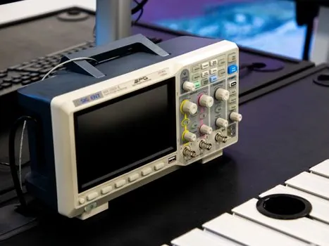
A calibration sticker with a date is not a certificate. The auditable artifact is a multi-page document naming the instrument model, serial number, the reference standard used (typically a traceable liquid-column or time-of-flight reference bench with stated uncertainty), the as-found and as-left error at multiple test points, and the temperature at which the calibration was performed. For an ultrasonic level meter destined for a high-temperature drum, the certificate's stated calibration temperature should be at or near the operating temperature of the vapor space, not a 20 °C bench number, because the speed-of-sound compensation is temperature-dependent and a 1 °C error in the assumed vapor temperature translates to a measurable level error at the meter output [S1].
Three practical checks: confirm the issuing lab's accreditation (ISO/IEC 17025 scope must list "level" or "time-of-flight ultrasonic"), confirm the certificate's stated uncertainty in mm or %FS at each test point and compare it to the supplier's published spec, and confirm the next-due date against the plant's own calibration interval. A certificate older than 12 months at the time of commissioning should trigger a re-check before lift, not after.
Options Comparison: Point-Level vs Continuous Ultrasonic vs Guided-Wave Radar on a Drum
Three sensing families compete for the drum-level slot, and the right call depends on which failure mode the plant most fears. Ultrasonic non-contact (air-coupled) is the lowest-cost and easiest to retrofit through an existing nozzle, but it loses accuracy in steam-turbulent or foaming conditions and typically requires a stilling well or target float for reliable drum service; guided-wave radar (TDR) penetrates foam and steam, costs 2–4× the ultrasonic option, and reads through the same nozzle size with no moving parts; point-level probes (vibrating-fork, capacitance, or conductivity) are the cheapest but only indicate "wet/dry" at a fixed elevation, which is acceptable as a low-water cutoff backup but not as the primary drum level [S1].
The comparison below lines the three against the decision criteria that actually matter on a saturated-drum duty:
Ultrasonic (air-coupled) is the lowest installed cost and fits existing 50–100 mm nozzles, but the published accuracy band is wider in steam-turbulent conditions and the wetted-face temperature ceiling is the first spec to fall below the drum saturation line; guided-wave radar handles foam, saturated steam, and high temperature with a published accuracy typically tighter than ultrasonic, at 2–4× unit cost and with rigid probe length constraints inside the drum; point-level is the right tool only as a low-water cutoff interlock, not as the controlling level transmitter. For a deeper primer on the radar alternative on high-temperature and high-pressure duties, the radar level meter reference walks through the foam-penetration and dielectric trade-offs that drive the choice between ultrasonic and TDR. Where the same foam-and-steam problem is solved in clean-piping service, the ultrasonic flowmeter reference gives a useful cross-check on how the same acoustic principle behaves on liquids versus vapors.
Installation and Commissioning Hold Points Specific to Drum Duty

For waste-heat-recovery and conventional fired drums, the same hold-point discipline that applies to the pressure parts applies to the level instrumentation: every nozzle, standoff, and gasket must be checked on the pre-commissioning walkdown, with weld records on file for any field-fabricated stand-off, and the first-light commissioning of the level loop must happen with the drum cold, at a known water level, and with the manways open enough to verify the indicated level against a physical tape measurement [S2].
Five items that consistently fail the audit and that should be on the pre-lift checklist: (1) the stand-off nozzle internal diameter matches the transducer's published mounting spec, (2) the gasket material is rated for the drum's peak temperature, (3) the transducer cable gland and conduit seal maintain the Ex rating through the boiler casing, (4) the temperature-compensation probe is physically close enough to the active transducer to see the same vapor column, and (5) the DCS engineering range, engineering units, and alarm setpoints are loaded into the controller before first firing, not on first steam [S1][S2].
Common Failure Modes and the Field Signals That Reveal Them
Four failure patterns dominate the field data on drum ultrasonic level meters, and each one has a trackable signal. False-high reading from condensation on the transducer face shows up as a slow drift upward over hours, and is solved by an air-purge ring or a higher-temperature-rated face material; foam-induced total loss of echo shows up as a flatlined output and is the single most common reason plants retrofit to guided-wave radar; high-temperature electronic drift shows up as a calibration-creep signature that re-aligns only on a cold drum and diverges again as the drum heats; and false-low reading from a blocked or partially blocked stand-off nozzle shows up as a level reading that follows steam demand but with a constant offset [S1].
Trending the as-found vs as-left error on every scheduled calibration, not just the pass/fail line, is the cheapest diagnostic against all four of these, because the shape of the drift tells the maintenance planner which of the four is the actual root cause. For plants that also need acoustic measurement of stack or casing noise on the same boiler, the sound level meter reference is a useful cross-check on microphone-style acoustic devices in hot, dirty enclosures.
What This Certification Is, and What It Is Not, For
This checklist is for a continuous ultrasonic level transmitter specified as the primary drum-level loop on a saturated-steam boiler in a power plant, refinery, or large WHRB installation, where the sensor body must survive continuous wetted-face temperature at or above the drum saturation line and the area classification is Zone 1 or Zone 2. It is not for low-pressure hot-water boiler drums operating below 120 °C, where a general-purpose tank sensor with a 70–80 °C face rating is fit for purpose, and it is not for low-water cutoff service, which is a separate safety-instrumented-function loop with its own SIL rating and proof-test interval under IEC 61511. [S1]
The signals to watch over the next 6–12 months are updates to the IEC 60079 family of standards for gas-detection and Ex equipment that touch ultrasonic housings, and the next revision cycle of ASME BPVC Section I instrumentation and alarm-sensor language that covers drum-level transmitter independence from low-water cutoffs. Two useful related reading tracks are the parallel certification discipline for outdoor electronic scale certification against corrosion exposure, which carries the same "is the cert really in scope" pattern, and the safety interlock switch selection for chemical plants, which applies the same hold-point logic to a different SIL-rated loop.