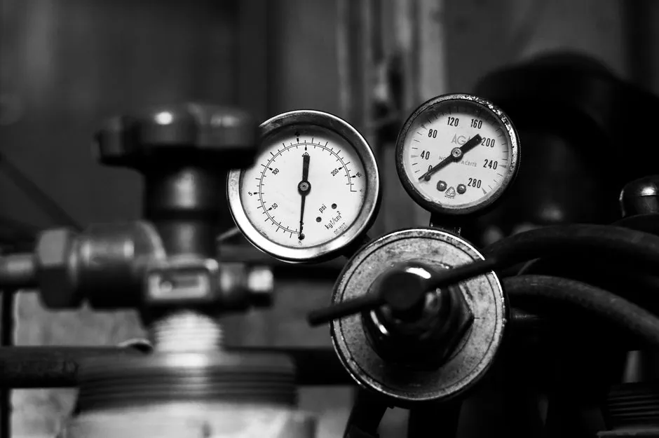
Vortex flowmeters operate with no moving parts across 8-13,363 kg/h mass flow and 0-300 °C process temperatures, while thermal gas mass flow controllers cover micro-ranges from 0-5 sccm up to 100-200 L/min with ±1.0% accuracy [S1][S3].
The two technologies target almost non-overlapping jobs: vortex meters serve saturated steam, superheated steam, and large-bore gas or liquid lines, whereas gas mass flow controllers (MFCs) are specified for low-flow clean gas dosing, blending, and closed-loop flow regulation. Choosing wrong wastes both capital and accuracy budget.
Operating Envelope: Where Each Technology Physically Lives
Vortex meters with differential-pressure compensation span process pressures from 10,100 Pa to 35,000,000 Pa (1.46-5,076.32 psi) and process temperatures from 0 °C to 300 °C, covering the full saturated-steam envelope from light to high-pressure service [S1]. Volumetric flow ceilings on the same meter reach 4,210 m³/h (148,674.75 ft³/h) on the high end, with a turndown floor of 2 m³/h, a roughly 2,000:1 span before compensation [S1].
Gas mass flow controllers built on thermal-mass sensing typically operate between 5 °C and 65 °C with a maximum line pressure of 3.0 MPa and a differential-pressure rating below 0.3 MPa across the element [S3]. The flow window is micro-scale by design: 0-5 sccm at the low end and 100-200 L/min at the high end, with a documented minimum range of 0-5 sccm for hydrogen-style service [S3]. A standard vortex flowmeter cannot resolve sccm-level flows, and a thermal MFC cannot survive 300 °C steam, so envelope alone disqualifies most cross-spec attempts.
Accuracy, Turndown, and Output Signal: The Numbers That Decide
The Azbil MVC3 / STEAMcube vortex platform quotes 0.2% and 0.3% precision classes with simultaneous analog and pulse output, and integrates an internal steam table so density is derived from the static-pressure sensor rather than from an external temperature probe [S1]. That dual-sensor topology gives the meter the responsiveness to track steam-trap transients that defeat conventional temperature-compensated vortex designs [S1].
Thermal gas mass flow meters from Chinese OEM lines are specified at standard accuracy 1.0%, with output choices of 0-5 V, 4-20 mA, and RS485/232 over a 12-24 V supply [S3]. Accuracy grade on the MFC side is therefore roughly 3-5x looser in percentage terms, but the absolute error at sccm flows is micrograms per second, which is the right resolution for the application. RS485/232 is a digital multi-drop bus, not a 4-20 mA current loop replacement; the 4-20 mA option on the MFC is the conventional analog current loop used in legacy DCS I/O [S3].
Working Principle and What It Implies for the Process
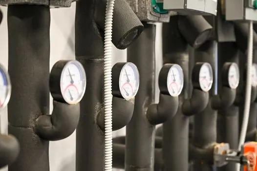
A vortex flowmeter works by shedding alternating vortices from a bluff body in the flow stream; frequency is proportional to velocity, and a static-pressure sensor compensates density for mass flow on steam service [S1]. The bluff-body design has no moving parts, which is why it is rated for 0.2-0.3% precision with low failure rates and is fielded on saturated steam, natural gas, ammonia, nitrogen, CO2, methane, demineralized water, compressed air, and crude methanol up to 100 cP [S1][S2].
A thermal gas mass flow controller works by measuring heat transfer from a heated sensor to the gas stream; mass flow is inferred from the cooling effect, which is directly proportional to mass (not volumetric) flow. The same unit can be wired to a control valve to close the loop, which is why the OEM literature describes the device as both meter and controller on a single 6 mm ferrule connection [S3]. For a broader view of where the meter family sits in the flow-instrument landscape, see the flow-meter reference page.
Selection Criteria: Vortex vs Thermal Gas Mass Flow Controller
For process engineers, the decision matrix collapses to four criteria: medium phase, flow magnitude, control requirement, and operating temperature/pressure. Vortex wins on steam and high-Reynolds gas/liquid service, on high temperature, on high pressure, and on installations with short straight-pipe runs, because STEAMcube-class designs cut required upstream straight-pipe length substantially [S1][S2].
Thermal mass flow controllers win on clean-gas micro-flow, on closed-loop mass-flow control, on multi-gas flexibility (the same meter body can be re-calibrated for different gases because the measurement is mass-based), and on installations where a 6 mm ferrule and 24 VDC supply are easier than a 4-20 mA loop and a 1-2" flanged body [S3]. For deeper gas-side theory, the thermal mass flowmeter encyclopedia entry and the gas mass flow controller reference cover the sensor physics, valve authority, and typical bypass architectures.
What Each Technology Is NOT For
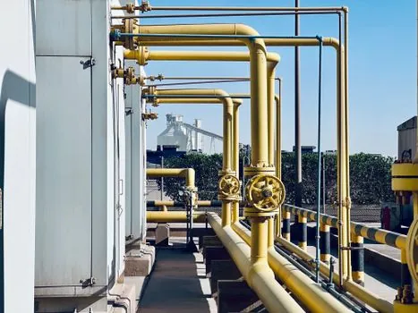
Vortex flowmeters are not recommended for batching, intermittent flow, low-pressure gas service, or sludge/slurry service; the bluff body fouls and the low-Reynolds flow loses vortex coherence [S2]. They also cannot resolve sub-m³/h flows where thermal mass flow controllers are still linear.
Thermal gas mass flow controllers are not specified for liquids, for steam, for dirty or wet gases without filtration, or for line temperatures above roughly 65 °C on standard builds [S3]. They are also not field-repairable in the same way a vortex body is, because the sensor element, capillary tube, and control valve are calibrated as a set; the OEM documents a working life of more than 3 years for the standard unit [S3]. Steam and hydrocarbon-vapor service at process temperature belong on a vortex flowmeter platform, full stop.
Real Use Cases and Integration Notes
Steam-cube-class vortex meters are fielded in power-plant saturated-steam lines, chemical-facility steam distribution, biotech and semiconductor demineralized-water skids, HVAC, food processing, and dust-control compressed-air lines [S1][S2]. The 0.2% precision and dual-sensor compensation make them suited to mass-flow steam metering where fiscal-grade accuracy matters.
Thermal mass flow controllers show up in semiconductor process-gas panels, fuel-cell hydrogen blending, odorizing injection, battery formation, and laboratory gas-blending skids, with documented export coverage in more than 100 countries across polyurethane, automotive, dispensing robots, battery, telecom, petroleum, chemical, coal, metallurgy, water, food, and medical sectors [S3]. For higher-pressure and higher-accuracy gas service where Coriolis becomes economical, the Coriolis flowmeter encyclopedia page documents the alternative path. For a complete spec-driven selection walkthrough on the vortex side, the Vortex Flowmeter 2026 Buying Guide lays out body material, lining, and output-card options in more detail.
Sourcing and Standards Discipline
Verify each vendor's accuracy claim against the published test protocol (typically ±0.6-1% for industrial thermal MFCs and 0.2-0.3% for differential-compensated vortex) and confirm pressure/temperature ratings against the worst-case operating point, not the nominal point [S1][S3]. On the gas-mass-flow side, watch the supply-voltage option: 220 VAC builds and 24 VDC builds are different SKUs, and the RS485/232 digital option is not interchangeable with a Foundation Fieldbus or PROFIBUS PA card [S3].
Track the next two signals: published updates to the Azbil STEAMcube precision class (currently 0.2%/0.3%) and any new 3.0 MPa-class thermal MFC release that pushes above the 65 °C ambient ceiling documented for current OEM units. Both data points would shift the crossover line between the two technologies in 2026 spec work.