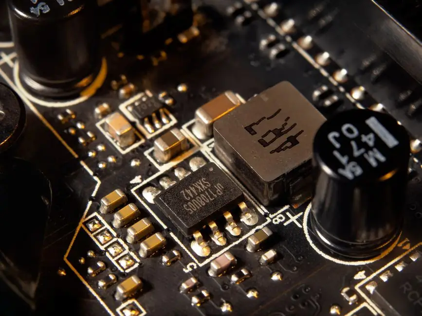
Yttria-stabilized zirconia polycrystal (Y-TZP) delivers flexural strength above 1000 MPa, fracture toughness 7-10 MPa·m½, and volume resistivity above 10¹⁴ Ω·cm, which is why electronics teams now specify it where 96% alumina cracks or FR-4 drifts in RF [S2][S3].
Engineers evaluating zirconia ceramic for substrates, insulators, sensor carriers, and structural blocks in 2026 are balancing four trade-offs: toughness vs thermal conductivity, dielectric loss vs cost, CTE match to silicon, and machining tolerance. The reference numbers below come from manufacturer datasheets published in 2025-2026 and a side-by-side test report comparing zirconia PCB to FR-4 at 2.4 GHz [S2][S3][S5][S6].
Material baseline: what Y-TZP actually delivers
Yttria-stabilized tetragonal zirconia polycrystal (Y-TZP) is the dominant electronics-grade formulation, with 3 mol% Y₂O₃ as the typical stabilizer; the transformation-toughening mechanism raises K_IC to 7-10 MPa·m½ versus 3-4 MPa·m½ for alumina, the single largest reason engineers pull zirconia into a design when impact or vibration is in scope [S2][S8].
Bulk density sits at 6.00-6.05 g/cm³, Vickers hardness at 1200 HV (about 13 GPa), and Young's modulus near 200 GPa; these numbers come from GB/T 25995, GB/T 16534, and GB/T 6569 test methods on Y-TZP lots from Dayoo, GGS, and similar Chinese suppliers [S3][S4]. Compressive strength lands at 2000 MPa and flexural strength at 1200 MPa for high-purity blocks, with the more conservative "≥1000 MPa flexural" claim that shows up across multiple datasheets reflecting minimum-acceptance rather than typical [S3][S4][S5].
Electrical and thermal envelope vs alumina
Zirconia carries a dielectric constant of 9.5-10.5 at 1 MHz and a dielectric loss tangent around 0.0005, which is the reason a 2.4 GHz microstrip on a zirconia substrate measured 0.37 dB insertion loss against 2.77 dB on FR-4 in a side-by-side published test, a roughly 7× gap that matters in mmWave front-ends and antenna arrays [S5].
Thermal conductivity is zirconia's weak axis: 2-3 W/m·K for typical Y-TZP is roughly an order of magnitude below alumina ceramic at 20-30 W/m·K, so for high-power LED boards, IGBT baseplates, and any heat-flux above about 5 W/cm² the default substrate is still 96% alumina, and aluminum nitride (AlN, around 170 W/m·K) for the worst cases [S2][S7]. Zirconia's CTE of 6.5-10.5 × 10⁻⁶/°C, depending on formulation and reference temperature, lines up with silicon (about 3-4 × 10⁻⁶/°C) more loosely than AlN does, but closely enough that direct-chip-attach and sensor-carrier builds use zirconia where alumina's 7-8 × 10⁻⁶/°C mismatch is also acceptable but the toughness floor is not [S2][S5][S7].
Selection criteria by electronics application

For ceramic PCBs, sensor carriers, and hybrid-circuit substrates, prioritize dielectric constant band (9.5-10.5), volume resistivity (10¹²-10¹⁴ Ω·cm), and a maximum service temperature; zirconia PCB datasheets from iPCB rate the use range at -269°C to 850°C and continuous high-temperature tolerance around 1000°C, with a 0.1 mm line/space process capability for fine-pitch circuits [S5].
For structural-insulator roles (precision guides, brackets, wafer-handling parts, RF insulators), prioritize flexural strength ≥1000 MPa, K_IC ≥ 7 MPa·m½, and thermal-shock ΔT around 250°C; GGS publishes K_IC at 17 MPa·m½ on a premium lot and 250°C ΔT, while Dayoo publishes 12 MPa·m½ with thermal-shock resistance rated "excellent" under GB/T 16534/GB/T 25995 protocols [S3][S4].
For smartphone back covers and signal-transparent enclosures, the published Y-TZP benchmark is bending strength ≥ 800 MPa with EM transparency for 5G/Wi-Fi 6E/7 bands; ADCERAX's AT-YHG-SJ001 catalogue item targets that envelope specifically, and the same toughness rationale lets a 0.5 mm cover survive drop tests that would crack a glass cover of equal thickness [S6]. For general industrial ceramic framing of where these lots sit, the broader taxonomy helps engineers pick between zirconia, alumina, and SiC up front.
Where zirconia loses to alternatives
Zirconia is the wrong pick when heat removal dominates, since 2-3 W/m·K is roughly 10× below alumina; power-module DBC substrates, high-brightness LED boards, and laser-diode mounts should stay on alumina or move to AlN [S2][S7].
Zirconia is also the wrong pick when the budget is tight and toughness is not required, since alumina ceramic at 96% purity typically lands 30-50% below Y-TZP per cm³ and machines faster with lower diamond-tool wear; for general-purpose insulators and wear pads, alumina is still the default [S8]. Zirconia PCB fabrication cost is also higher than FR-4 by roughly an order of magnitude at low volume, so the RF case (the 0.37 dB vs 2.77 dB at 2.4 GHz result) needs to clear a real engineering hurdle, not just look good on a slide [S5].
Machining, tolerances, and sourcing signals
Zirconia tolerates tight machining when the shop is set up for it: GGS publishes ±0.005 mm tolerance capability on custom structural blocks, and iPCB publishes 0.1 mm line/space on zirconia PCB, both backed by ISO 9001:2015 and (for GGS) IATF 16949:2016, with the latter relevant for any design that will end up in an automotive electronics or sensor module [S4][S5].
Sourcing signals in 2026 point to a maturing Chinese supply base for Y-TZP substrates, blocks, and PCBs, with multiple ISO 9001:2015-certified vendors (Dayoo, GGS, iPCB) publishing overlapping but not identical spec ranges; the practical move is to lock the test standard (GB/T 25995 for density, GB/T 16534 for hardness, GB/T 6569 for flexural strength) into the PO so "≥1000 MPa" means the same thing on both sides, and to require a K_IC sample-report, not just a flexural number [S3][S4][S5].
Trackable next node: watch for IEC/IEEE-qualified zirconia substrate datasheets entering 2027 power-electronics roadmaps, and compare incoming-lot K_IC against the 7-10 MPa·m½ baseline before approving a new vendor, since that is the property alumina cannot match and the reason zirconia is specified at all.
For related coverage, see Polyurethane insulation selection for hospital and ICU envelopes.