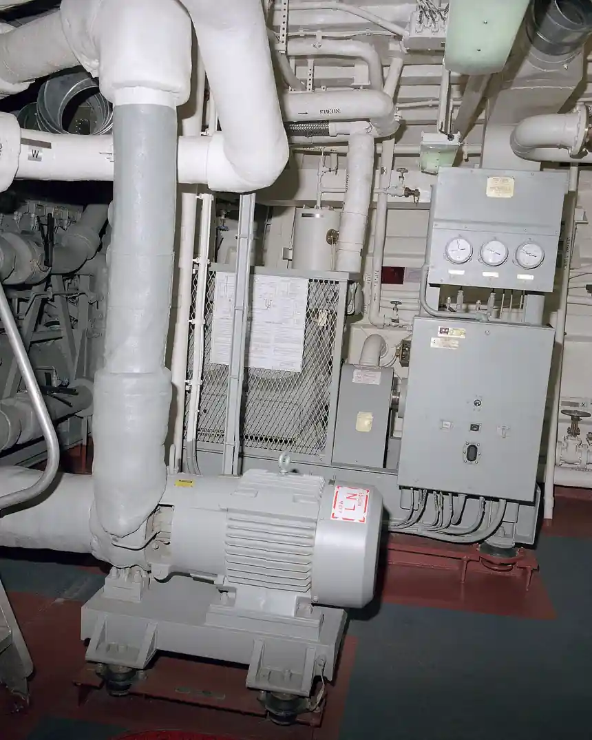
Marine heating, ventilation, and air conditioning (HVAC) encompasses the equipment, ductwork, controls, and water systems that provide thermal comfort, process cooling, and safe breathable atmospheres on vessels and offshore units. Unlike land-based systems, marine HVAC must tolerate constant vessel motion, structural vibration, salt-laden intake air, restricted machinery spaces, and the need to integrate with the ship's electrical, fire, and damage-control systems. Cooling capacities for shipboard equipment range from small self-contained cabin units of a few kilowatts to plant rooms serving entire superstructures with hundreds of kilowatts of sensible and latent load.
Specifying marine HVAC requires attention to classification society rules (such as ISO, ABS, DNV, and other recognized bodies), refrigerant management regulations, and the practical realities of dry-dock intervals, spares holdings, and crew competence. Equipment manufacturers publish capacity ranges and configuration options that allow naval architects, shipyards, and ship owners to match the HVAC plant to the vessel mission, ambient design conditions, and acoustic or redundancy targets. The chapters that follow summarize the working principles, parameter ranges, configurations, selection logic, compliance regime, and market practice that govern this equipment category.
Marine HVAC systems condition air aboard ships, offshore platforms, and other floating structures. They combine refrigeration, air handling, and corrosion-resistant construction to deliver cooling, heating, ventilation, and humidity control in salt-laden, vibrating, space-constrained environments. The discipline draws on the same vapor-compression cycle as building HVAC, adapted to seawater heat rejection, classification rules, and shipboard installation practice.
Chapter 1 / 06
Fundamentals and Working Principle
Marine HVAC systems are built around the vapor-compression refrigeration cycle, in which a refrigerant absorbs heat at low pressure in an evaporator and rejects it at high pressure in a condenser, with a compressor providing the pressure lift and an expansion device completing the loop. On ships, the condenser is most commonly cooled by seawater drawn through sea chests, strainers, and box coolers, although air-cooled condensers are used in certain weather-exposed or auxiliary applications. The evaporator is paired with an air-handling section that moves conditioned air through supply ductwork to the served spaces, while return air is filtered and either recirculated or partially exhausted depending on ventilation requirements.
Heat transfer in the evaporator coil is governed by the mass flow rate of air passing through the coil and the change in air enthalpy across the coil. Sensible load is removed by reducing the dry-bulb temperature of the air, while latent load is removed by condensing moisture out of the airstream. Marine applications typically see sensible heat ratios between 0.70 and 0.85, reflecting the high latent load contributed by warm, humid outside air and by moisture infiltration through doors, hatches, and machinery ventilation. Designers therefore specify coils and face velocities that balance sensible and latent capacity against condensate management and air-side pressure drop.
Seawater-cooled condensers require careful hydraulic design. The required seawater mass flow follows from the condenser heat rejection, seawater density, specific heat, and allowable temperature rise. Typical seawater temperature rise through a marine condenser ranges from 5 to 8 degrees Celsius, and tube velocities are held near 2.0 to 2.5 metres per second to deter biofouling while limiting erosion of copper-alloy or titanium tubes. Where seawater quality is poor, or where maintenance access is limited, plate heat exchangers and box coolers isolate the refrigerant side from the sea, allowing the refrigerant to be cooled by a closed freshwater loop that in turn rejects heat to seawater.
Beyond the refrigeration cycle, marine HVAC integrates ventilation, filtration, and sometimes humidification. Ventilation rates are dictated by crew occupancy, engine exhaust proximity, battery compartment hydrogen dilution rules, and classification society habitability requirements. Filtration typically includes salt-coalescing prefilters ahead of cooling coils, particulate filters for recirculated air, and carbon or specialty filters for galley, hospital, or hazardous-area spaces. Where heating is required, marine plants commonly use hot water from the engine jacket cooling circuit, steam from an auxiliary boiler, or electric resistance elements, with the choice driven by the vessel's overall energy balance.
Vapor-compression refrigeration with seawater-cooled condenser is the dominant configuration
Sensible heat ratio for marine applications typically 0.70 to 0.85
Seawater temperature rise through condenser 5 to 8 degrees Celsius
Seawater tube velocity held near 2.0 to 2.5 metres per second
Chapter 2 / 06
Specifications and Key Parameters
Marine HVAC equipment is specified across a wide envelope of capacities, geometries, and refrigerant choices. Compact self-contained units start at roughly 1 to 5 tons of refrigeration (3.5 to about 17.5 kW) for individual cabins and small offices, while integrated plants serving engine rooms, galleys, and accommodations can exceed 100 tons (roughly 350 kW) for a single vessel. Marine-grade construction is mandatory, and suppliers identify their equipment as compliant with one or more classification standards such as ISO, ABS, or DNV, which dictate material selection, pressure testing, vibration testing, and documentation. Refrigerant selection follows both the required capacity and current environmental regulation, with common choices including R-22 (in legacy systems), R-410A, and R-134a, each with its own viscosity, glide, and lubricant compatibility profile.
Marine air handling units (AHUs) cover an even wider capacity range because they can be paired with remote chillers, heat recovery loops, or direct-expansion refrigerant circuits. According to HISURP product specifications, a marine AHU can be configured for chilled water, direct expansion, or heat recovery, and can deliver airflow from 1,000 to 50,000 cubic metres per hour, cooling capacity from 5 to 300 kW, and heating capacity from 3 to 200 kW. These envelopes reflect the diversity of vessel sizes from small patrol craft to large passenger ships, offshore support vessels, and platform accommodation units, and they illustrate how a single AHU architecture can be scaled and reconfigured to suit multiple applications.
The packaged unit category subdivides further by geometry and installation. Compact wall-mount units deliver 3.5 to 10.5 kW with seawater cooling and are installed through bulkheads into cabins. Deck-mounted horizontal units cover 10.5 to 35 kW and serve crew quarters and mess halls, mounted above overheads in passageways. Vertical floor-mounted units deliver 17.5 to 70 kW for large spaces and control rooms, while split packaged units span 35 to 105 kW for bridge and operations centres with remote condensers. Modular air handlers reach 70 to 175 kW using a separate chiller, and self-contained rooftop units cover 35 to 140 kW with air-cooled condensers for weather-deck spaces.
Refrigerant viscosity, charge size, and lubricant carry-over all influence marine HVAC specification. Refrigerant viscosity varies by type, and the chosen lubricant (mineral oil, alkylbenzene, polyolester, or polyvinyl ether) must be miscible with the refrigerant across the operating envelope. Charge minimization matters because the International Convention for the Prevention of Pollution from Ships and classification rules restrict refrigerant quantities, leak rates, and recovery procedures. Designers select hermetic, semi-hermetic, or open-drive compressors based on capacity, maintenance philosophy, and the ability to field-service the unit in remote ports; open-drive compressors with integral oil separators remain common in larger plants where service access and parts availability favor them.
Parameter
Range (per S1, S2, S3, S4 as noted)
Capacity, compact self-contained units
1 to 5 tons (compact) up to 100+ tons (large) (S1, S2)
Capacity, packaged wall-mount (S3)
3.5 to 10.5 kW
Capacity, packaged deck-mounted horizontal (S3)
10.5 to 35 kW
Capacity, packaged vertical floor-mounted (S3)
17.5 to 70 kW
Capacity, packaged split (S3)
35 to 105 kW
Capacity, packaged modular air handler (S3)
70 to 175 kW
Capacity, packaged self-contained rooftop (S3)
35 to 140 kW
Marine AHU airflow (HISURP, S4)
1,000 to 50,000 m^3/h
Marine AHU cooling capacity (HISURP, S4)
5 to 300 kW
Marine AHU heating capacity (HISURP, S4)
3 to 200 kW
Condenser cooling methods (S3)
Seawater-cooled or air-cooled
Seawater temperature rise through condenser (S3)
5 to 8 degrees Celsius
Seawater tube velocity (S3)
2.0 to 2.5 m/s
Sensible heat ratio, typical (S3)
0.70 to 0.85
Common refrigerants cited (S1, S2)
R-22, R-410A, R-134a
Construction grade (S1, S2)
Marine-grade, corrosion-resistant; ISO, ABS, DNV, or other classification compliance
Chapter 3 / 06
Types and Configurations
Marine HVAC equipment is conventionally grouped into self-contained packaged units, split systems, central chilled-water plants, and dedicated ventilation/air-handling systems. Self-contained packaged units integrate the compressor, evaporator, condenser, and air-moving equipment inside a single cabinet; the through-bulkhead wall-mount is a familiar example, in which the evaporator section projects into the conditioned space while the condensing section sits in a service corridor or on an exterior bulkhead. The chief benefit is simplified installation, reduced refrigerant charge, and zone-level redundancy, since the loss of one unit affects only the space it serves.
Split packaged systems separate the evaporator and condensing sections, with refrigerant piping running between them. This is the preferred configuration where the condenser must be located in a machinery space away from the served compartment, or where acoustic and vibration isolation of the occupied zone is essential. The evaporator is installed in or above the bridge, operations centre, or main salon, while the seawater-cooled condenser is placed in an engine room or auxiliary machinery space where heat rejection is easier and service access is unrestricted. Modular air handlers extend this approach further by combining a large central air handler with a dedicated chiller, enabling the air side to be optimized independently of the refrigerant side.
Central chilled-water plants, also known as district cooling or water-cooled chiller plants, are the standard solution for larger vessels such as cruise ships, naval auxiliaries, offshore support vessels, and platform accommodation. Chilled water is produced by one or more marine chillers and circulated by pumps through a piping loop to fan coil units, air handling units, and process coolers throughout the ship. The arrangement allows multiple chillers to share load, provides N+1 redundancy with appropriate valving, and centralizes the seawater interface in a single machinery space. The trade-off is the additional complexity of pumps, expansion tanks, glycol loops where freeze protection is needed, and a larger volume of piping insulation.
Marine AHUs are configured for chilled water, direct expansion, or heat-recovery operation. Chilled-water AHUs are most common on vessels with central plants. Direct-expansion AHUs are used where the plant is decentralized or where the AHU serves a critical zone that must be self-sufficient. Heat-recovery AHUs recover energy from exhaust air or from engine jacket water to provide heating, reducing the demand on boilers and electric heaters. Across all of these types, the cabinet is built from marine-grade materials such as galvanized steel with epoxy coatings, stainless steel, or aluminum alloys, with anti-vibration mounts, drip-proof or weatherproof enclosures rated for the installation space, and access panels sized for the confined spaces typical of shipboard equipment rooms.
Self-contained packaged units for cabins and small compartments
Split packaged units with remote condensers for occupied or noise-sensitive spaces
Modular air handlers paired with dedicated chillers for large central systems
Central chilled-water plants with multiple chillers and a piping loop serving many fan coil units
Heat-recovery AHUs using engine jacket water or exhaust air as heat sources
Chapter 4 / 06
Selection Criteria for Procurement
Procurement of marine HVAC equipment starts with a clear definition of the design heat load, ventilation requirement, and ambient conditions. The cooling load is calculated from the vessel's operating profile, taking into account solar gain through superstructure, internal gains from lighting, engines, galleys, electronics, and crew occupancy, and the latent load from outside air, cooking, and breathing. Ventilation requirements are set by classification rules and flag-state regulations, and they determine the volume of outside air that must be conditioned. Designers then choose a unit envelope, redundancy strategy, and control architecture that meets the load at design conditions with margin for fouling, partial equipment failure, and extreme climate operation.
Physical and operational constraints heavily influence equipment selection. Available space, headroom, and access routes into machinery spaces or above ceilings often determine whether a packaged, split, or modular configuration can be installed. Weight and center-of-gravity considerations matter on smaller vessels, and shipyards routinely specify that any equipment heavier than a threshold must be placed on a designated foundation with approved welding or bolting details. Serviceability is also a procurement factor: hermetic compressors cannot be field-serviced, while semi-hermetic and open-drive compressors allow valve plate and bearing replacement, which can be attractive for vessels operating far from OEM service networks.
Materials of construction and corrosion protection are key differentiators. Marine HVAC exposed to salt spray, bilge moisture, and engine room atmospheres requires marine-grade corrosion-resistant construction. Suppliers identify their equipment as compliant with one or more recognized classification standards such as ISO, ABS, DNV, or other bodies, and procurement specifications typically require material certificates, weld procedure qualification records, and surface treatment schedules. Condenser tubes may be specified in copper-nickel, aluminum-brass, or titanium depending on seawater chemistry, with titanium favored for highly polluted or low-pH water. Coatings and cathodic protection of the seawater circuit are common additional requirements.
Control, monitoring, and integration complete the procurement specification. Modern marine HVAC is integrated with the ship's alarm, monitoring, and control system, often through a serial or Ethernet-based protocol. Specifiers typically require that each unit provide status, running, and fault signals, that setpoints be adjustable from a central graphical display, and that safety functions such as low refrigerant pressure, high discharge temperature, and seawater flow loss trigger both local and remote alarms. Energy efficiency is increasingly evaluated through coefficient of performance and part-load performance curves, and shipowners may specify variable-speed fans and compressors, economizer cycles, and heat recovery to reduce fuel consumption.
Confirm design cooling load, ventilation rate, and ambient conditions
Match unit envelope to available space, weight limits, and access constraints
Verify marine-grade construction and classification compliance per project
Specify materials for seawater and salt-spray exposure
Require alarm, monitoring, and remote-control integration with ship systems
Chapter 5 / 06
Standards, Compliance, and Testing
Marine HVAC equipment is designed, manufactured, and tested against a framework of classification society rules, flag-state regulations, and international conventions. Suppliers identify their equipment as marine-grade and compliant with standards issued by classification societies such as ISO, ABS, DNV, or other recognized bodies. These rules cover pressure vessel design for refrigerant-containing components, materials traceability and certification, non-destructive testing of welds, electrical safety in hazardous areas, and environmental testing for vibration, inclination, and ambient temperature. The classification surveyor typically attends factory acceptance tests and reviews design documentation before the equipment is released for shipboard installation.
Refrigerant management is governed by the International Convention for the Prevention of Pollution from Ships and its annexes, particularly the requirements related to ozone-depleting substances and the F-Gas-style national regulations that apply in many flag states. These rules limit which refrigerants may be used, set maximum charge sizes for certain applications, require leak detection on systems above defined charge thresholds, and mandate proper recovery and disposal at the end of life. Procurement specifications must identify the refrigerant for each unit, and ship operators are responsible for maintaining leak records and ensuring that service technicians hold appropriate recovery certification.
Type testing and routine testing are central to marine HVAC compliance. Factory acceptance tests typically include a running test at design conditions to verify capacity, power input, and leaving air temperature, a leak test of the refrigerant circuit, an electrical insulation resistance and high-potential test, and a controls functional test. Class rules additionally require inclination testing, in which the unit is operated at static angles representative of vessel roll and pitch, and vibration testing using shakers or rotating-mass exciters to confirm that the equipment can survive shipboard mechanical stresses. Sea trials then verify that the system delivers the specified air temperatures and ventilation rates on the actual vessel.
Operational compliance continues after delivery. Crews are responsible for routine maintenance such as cleaning seawater strainers, inspecting anodes, changing filters, and checking refrigerant charge. Classification surveyors periodically inspect the equipment and may require thickness measurements of pressure components, calibration of safety devices, and review of maintenance logs. Where the vessel operates internationally, port state control officers can verify that documents including the International Air Pollution Prevention Certificate, classification certificates, and safety equipment records are current. Together, these regimes ensure that marine HVAC continues to deliver safe, reliable performance throughout the vessel's service life.
Classification society rules from bodies such as ISO, ABS, DNV, or others
Refrigerant controls under MARPOL and F-Gas-style national regulations
Factory acceptance tests for capacity, leakage, electrical safety, and controls
Inclination and vibration testing per class requirements
Periodic class surveys and flag-state air pollution prevention certification
Chapter 6 / 06
Market Landscape and Buying Process
The marine HVAC market is served by a mix of global OEMs, regional system integrators, and shipyard-owned engineering teams. Large multinationals supply central chilled-water plants and high-capacity air handling units to cruise lines, navies, and offshore operators, while regional manufacturers supply packaged units, fan coil units, and cabin self-contained equipment to commercial shipyards. Some suppliers, such as HISURP, position themselves as China-based manufacturers of marine HVAC equipment offering customized marine AHU solutions, and they list capacity ranges that overlap significantly with the broader category. Buyers therefore evaluate suppliers on classification credentials, reference vessel lists, service network reach, and the ability to customize units within the shipyard's installation envelope.
The buying process typically begins with a request for quotation that includes the vessel particulars, classification society, flag state, design ambient conditions, heat load summary, ventilation rates, and any constraints on space, weight, or noise. Suppliers respond with technical proposals, general arrangement drawings, refrigeration and electrical schematics, and a commercial offer. Shipyard or owner teams review the proposals against the specification, perform commercial evaluation, and may enter a clarification phase to resolve questions on capacity margins, control integration, spare parts, and documentation. Once a vendor is selected, a kickoff meeting is held to finalize the technical schedule, after which approval drawings are produced and the units enter fabrication.
Lead times for marine HVAC equipment depend on capacity, customization, and classification. Standard packaged units and fan coil units can be delivered in a few weeks to a few months, while central chiller plants, large AHUs, and customized systems typically require several months of engineering and fabrication, with extended periods for owner-furnished equipment that must interface with other ship systems. Delivery terms under Incoterms define responsibilities for transportation, insurance, and customs clearance, with CIF and DAP terms common for cross-border shipments to shipyards in Korea, China, Japan, or Europe. Service support, warranty terms, and the availability of commissioning engineers are increasingly important differentiators in a market where vessels operate worldwide.
Aftermarket support is a significant component of the marine HVAC value proposition. Suppliers provide spare parts kits tailored to the installed unit list, offer onboard service for warranty and post-warranty work, and maintain regional workshops to overhaul compressors, replace coil bundles, and rebuild control panels. Many shipowners enter multi-year service agreements that include scheduled maintenance, performance verification, and a guaranteed response time for unscheduled calls. Training of shipboard crew and shoreside technical staff is also part of the package, covering routine tasks, refrigerant handling, and basic troubleshooting. The combination of engineered equipment, classification compliance, and global service support defines how marine HVAC is bought, installed, and sustained over the operational life of the vessel.
OEMs, regional integrators, and shipyard engineering teams participate in the market
RFQ cycle covers technical, commercial, and documentation review
Lead times range from weeks for packaged units to months for central plants
Incoterms define delivery, insurance, and customs responsibilities
Aftermarket service agreements, spares, and crew training sustain long-term operation
FAQ
What is the difference between a self-contained marine HVAC unit and a split system?
A self-contained unit places the compressor, evaporator, condenser, and air mover inside a single cabinet and is typically installed through a bulkhead or on a deck, with the refrigerant circuit factory sealed. A split system separates the evaporator and condenser, with refrigerant piping run between them so the condenser can sit in a machinery space while the evaporator serves an occupied or noise-sensitive compartment. Self-contained units are simpler to install and require less refrigerant; split systems offer better acoustic isolation and easier service access.
Why is seawater cooling the dominant condenser method on ships?
Seawater provides a stable, year-round heat sink that is independent of ambient air temperature, which is critical for vessels operating in tropical and equatorial waters. Seawater-cooled condensers reject heat efficiently, can be sized for high capacities, and use sea chests and box coolers that isolate the refrigerant circuit from the sea where required. Typical designs hold the seawater temperature rise through the condenser at 5 to 8 degrees Celsius and tube velocity near 2.0 to 2.5 metres per second to balance heat transfer against biofouling and erosion.
Which refrigerants are commonly used in marine HVAC, and why does the choice matter?
Common refrigerants cited for marine air conditioning include R-22 in legacy systems, R-410A in newer split and packaged units, and R-134a across a wide range of equipment. The choice matters because refrigerant viscosity, glide, and lubricant compatibility differ between products, and because international and flag-state regulations restrict ozone-depleting substances and impose leak detection and recovery requirements on systems above defined charge thresholds. Procurement specifications typically fix the refrigerant to allow the ship operator to standardize training, spares, and recovery equipment.
How is marine HVAC equipment shown to comply with safety and classification rules?
Suppliers identify their equipment as marine-grade and compliant with classification standards such as ISO, ABS, DNV, or other recognized bodies, and they provide supporting documentation including material certificates, weld records, and design calculations. Equipment is typically subjected to factory acceptance tests covering capacity, leak integrity, electrical safety, and controls, plus class-required inclination and vibration testing. After installation, classification surveyors and flag-state authorities continue to inspect the equipment periodically and review maintenance records over the vessel's service life.
What capacity range should a buyer expect when specifying a marine air handling unit?
According to HISURP product specifications, a marine AHU can be configured for chilled water, direct expansion, or heat-recovery operation, and it can deliver airflow from 1,000 to 50,000 cubic metres per hour, cooling capacity from 5 to 300 kW, and heating capacity from 3 to 200 kW. The wide envelope allows the same architecture to serve small craft, large offshore vessels, and platform accommodation. Buyers should select a specific model and configuration based on the heat load calculation, the available space, and the desired redundancy strategy.
What is the sensible heat ratio for marine applications, and why is it high?
The sensible heat ratio for marine applications typically ranges from 0.70 to 0.85, which is higher than many land-based applications. The value is driven by the high latent load contributed by warm, humid outside air, by moisture introduced through doors, hatches, and machinery ventilation, and by internal latent gains from cooking and breathing. Designers use this ratio to size cooling coils, select face velocities that manage condensate without carryover, and ensure that dehumidification is adequate for crew comfort and for the prevention of condensation on cold surfaces.
How do ship operators maintain marine HVAC over the service life of a vessel?
Shipboard maintenance includes routine tasks such as cleaning seawater strainers, inspecting sacrificial anodes, replacing filters, and checking refrigerant charge, supplemented by periodic classification surveys that may require thickness measurements of pressure components and calibration of safety devices. Many shipowners also enter multi-year service agreements with the equipment supplier to obtain scheduled maintenance, guaranteed response times for unscheduled calls, and access to spare parts. Crew training in refrigerant handling, basic troubleshooting, and emergency procedures is an essential part of sustaining reliable operation between dry-dockings.