
A 135° seismic hook is the most common stirrup and crosstie geometry specified for earthquake-resisting frames, and it is also the bend most often mis-fabricated on site because crews default the stop to 90° and ship it. Production-bent 135° hooks on a rebar bender require three matched settings: a programmed stop at 135°, a central bending pin at the code-required multiple of bar diameter (4d for standard hooks, 6d for stirrups and seismic ties per ACI 318 / AASHTO LRFD), and a straight leg extension of 6d past the bend [S4][S3].
Seismic hooks differ from standard 90° and 180° hooks in two measurable ways: the post-bend straight extension is longer in proportion to bar size (6d versus 4d for a 180° hook), and the hook is almost always closed against a cross-bar in a column tie, so angle accuracy directly controls concrete confinement. A 90° hook substituted for a 135° hook leaves the tie end pointing along the column axis, which loses the seat-of-hook bearing that the code intends [S3][S8].
Bend-Angle Programming: 0–180° Range, 1° Resolution, 135° as a Seismic Stop
A bender that holds a 135° seismic hook to within ±1° across a 200-piece production run is the practical floor for any column-cage or shear-wall project, and that is why the bridge-bender spec gates collapsed to a 0–180° programmable range with 1° increments as the minimum for any work that includes seismic ties [S4]. The IKK DBD-32X single-phase portable bender covers 0–180° on bars up to D32 mm at 560 N/mm² tensile strength, hitting 180° in 8 sec at 1500 W input (100/115/230 V selectable) from a 590 × 620 × 480 mm, 180 kg package [S1]. The Blades Direct MB25A covers the same 0–180° envelope on the smaller #3–#8 (9.5–25.4 mm) bar range from a 13 A, 115 V single-phase draw, with a 180° bend in roughly 5 sec on its rated diameter [S6].
The 135° stop is a subset of that envelope and is invoked wherever a stirrup, column tie, or boundary-element crosstie calls for a seismic hook, because at that angle the bent leg lands flat against the longitudinal bar it is confining. IS 2502:1963 fixes the 135° seismic hook at an extension of 6d, the 90° standard hook at 8d, and the 180° U-hook at 4d, which gives the operator three different post-bend straight-leg lengths to honour depending on the angle the stop is set to [S3][S7]. On a rebar bender, that means a single 180°-capable machine covers all three hook geometries, but the straight-leg length has to be marked or stopped separately because the bend head does not control it.
Mandrel / Central Pin Diameter: 4d Standard Hook vs 6d Seismic Hook
The internal bend diameter (mandrel, or central bending pin on a rebar bender) is the most frequently violated detail on a 135° seismic hook, because the bar is being bent to a sharper included angle than a 90° stop and the outer fibre strain scales with 1/r. IS 2502:1963 sets the minimum internal bend diameter for standard hooks at 4d for bars up to a defined size band and escalates it for larger diameters and higher grades, while ACI 318 Chapter 25 and AASHTO LRFD impose their own multiples of bar diameter tied to bar size, grade, and seismic category [S7][S3][S4]. For a typical stirrup in Fe-500 / Grade 60 stock, 4d is the code minimum for a standard 90° or 135° hook, and seismic-category detailing in high-ductility frames steps up to 6d on the same diameter bar [S4].
In practice, the pin set shipped with a portable rebar bender is the binding constraint, and most 25–32 mm-class machines are sold with a multi-piece pin kit so the operator can swap to 2d, 3d, 4d, or 6d without re-tooling the head. A 135° seismic hook on a #5 (16 mm) bar in a U.S. high-ductility column therefore uses a 96 mm (6 × 16) internal bend diameter, which is a noticeably larger radius than the 64 mm pin a standard 4d hook would call for, and the difference shows up as either a flat spot (pin too small) or a sprung-back angle (pin too large) on the finished tie [S4]. A field check that the pin is the right one for the seismic zone on the drawing catches more 135°-hook defects than any angle-gauge reading after the bend.
Capacity Bands, Drive Power, and Cycle Time at 135°
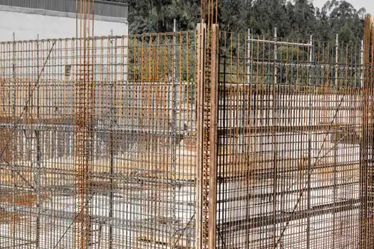
Three capacity tiers dominate 135°-hook production work: 10–25 mm (light landscape and small footings), 10–32 mm (general pier, cap, and column-cage work), and 10–42 mm (heavy main-bar bending on long-span decks and caisson cages) [S4]. The 10–25 mm tier covers the bulk of single-family and low-rise stirrup production, where 135° seismic hooks on #3 and #4 ties are bent thousands at a time on units like the MB25A [S6]. The 10–32 mm tier, represented by the IKK DBD-32X at 1500 W single-phase, covers column ties and boundary-element crossties in mid-rise commercial work and is the most common specification on Southeast Asian bridge tenders as of 2026 [S1][S4]. The 10–42 mm tier is reserved for main-bar seismic hooks on 36–40 mm longitudinal reinforcement in highway-overpass bents and large-diameter caisson cages, and is built around 3-phase hydraulic-drive benders in the 2.2–4.0 kW band such as the GW50 (4 kW / 5.5 HP, 20–25 rpm) [S4][S5].
A first-pass productivity gate for 135° production is motor power in kW per millimetre of rated bar diameter, with a healthy machine landing near 0.10–0.12 kW/mm: a 32 mm unit therefore needs 3.2–3.8 kW, and a 42 mm unit 4.2–5.0 kW [S4]. Single-phase 1.5–2.2 kW machines such as the DBD-32X or the hand-bender hydraulic class hit that ratio on 25–32 mm bars and stall on sustained 36 mm runs, which is why a 135° seismic hook on a 36 mm main bar is fabricated in a stationary shop on a 380–415 V three-phase bender rather than on a portable unit at the deck [S4][S2]. Cycle time on the rated bar is typically 5–8 sec for a 180° bend, so a 135° hook lands in roughly 4–6 sec per tie on a healthy machine, and any cycle creeping past 10 sec on the top diameter is the early warning of a worn central pin or under-rated motor [S1][S6].
Standard Hooks vs Seismic Hooks: Angle, Extension, and Pin Selection Compared
90° standard hooks, 135° seismic hooks, and 180° U-hooks can all be produced on the same 0–180° rebar bender, but each combination of angle, post-bend extension, and mandrel diameter maps to a specific code use case, and choosing the wrong row of that table is what gets rebar rejected at inspection. IS 2502:1963 is the most explicit reference: 90° hook with 8d extension, 135° hook with 6d extension, 180° hook with 4d extension, with mandrel diameters that escalate for larger bar sizes and higher steel grades [S3][S7]. A criteria-based comparison lines the three options up against the four gates that govern a rebar bender's day-to-day setup:
Hook angle vs use case: 90° for standard stirrup and tie ends, 135° for seismic stirrups, column ties, and boundary-element crossties, 180° for slab and beam end anchorage where maximum bearing is required [S3][S8]. Post-bend straight extension: 8d for 90°, 6d for 135°, 4d for 180° under IS 2502 [S3]. Mandrel / central pin: 4d for standard 90° and 180° hooks on most grade stock, 6d for 135° seismic hooks in high-ductility frames; pin set must be physically swappable on the bender head [S4][S7]. Machine envelope: any 0–180° programmable bender with a 1° increment covers all three, but capacity (10–25, 10–32, 10–42 mm) and drive power (1.5 kW single-phase portable to 4 kW three-phase hydraulic) scale to the bar diameter on the schedule [S1][S4][S5][S6]. The downstream consequence of getting one of those four rows wrong is a hook that cracks at the bend (pin too small), springs back past tolerance (pin too large or bar grade mismatch), or fails inspection because the extension measures 4d where 6d was specified [S4][S7].
Production Workflow on Site: Marking, Stop Setting, Pin Swap, and 6d Check
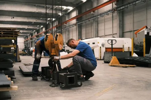
A 135° seismic hook on a rebar bender is set up in four steps that match the four spec gates above, and skipping any one of them is the most common path to a rehook-and-scrap outcome. Step one is to mark the straight-leg start point at 6d from the bar end, because the bend head does not control extension length; step two is to index the angle stop to 135° on the bender's dial and lock it; step three is to swap the central pin to the 6d (seismic) or 4d (standard) size called for on the drawing, and confirm it is fully seated; step four is to bend one trial piece and gauge both the included angle and the post-bend extension with a protractor and tape before running production [S4][S7].
For a column-cage or shear-wall run on D16–D25 mm stock, the MB25A-class 25 mm bender and the DBD-32X-class 32 mm bender are the units most crews will pull to a tie bench, and both reach the seismic 135° stop in a single indexing because their full envelope is 0–180° at 1° resolution [S1][S6]. For D32–D40 mm main-bar seismic hooks, the same workflow is run on a stationary GW50-class 4 kW three-phase hydraulic bender, where the larger motor and heavier pin set hold the 6d internal radius without flat-spotting the bar at the higher bending moment [S4][S5]. On any of those machines, a 135° stop is verified against an angle gauge after the first bend, and a springback correction of 1–2° is normal on higher-grade TMT or Grade 60 stock before the run is locked in [S3][S4].
Common Failure Modes on a 135° Hook and What They Tell You
A 135° seismic hook that comes off the rebar bender cracked on the outside fibre is a pin-diameter problem: the central bending pin is smaller than the code-mandated 4d (standard) or 6d (seismic) for the bar size, and the outer-fibre strain has exceeded the steel's bendability limit at that angle. A 135° hook that opens up past 140° after the bend is a pin-diameter problem in the opposite direction or a springback correction that was never dialled in, and on TMT Fe-500 / Fe-550 stock both effects are amplified relative to mild steel [S7][S3]. A 135° hook that measures exactly 135° but fails inspection on the 6d straight extension is a stop-and-mark problem: the angle is right, the leg is short, and the bender cannot fix it because the extension is set by the operator, not the machine [S4][S7].
The downstream consequence of any of those defects on a seismic tie is rework at the tie bench, and on a 200-piece column-cage run the cost is two to three days of crew time plus material scrap, which is the dollar figure that tends to get management attention when a 90° stop is shipped in place of a 135° stop on a boundary-element run [S8]. For poker vibrator selection alongside rebar cage work, see the 2026 field guide on poker vibrator diameter vs rebar clear spacing, which addresses the companion problem of getting consolidation into a tightly tied seismic cage without honeycombing the cover zone.
Trackable next signals for 135°-hook production work: published revisions to IS 2502 and ACI 318 Chapter 25 that would shift the 4d / 6d mandrel multiples for higher-grade TMT stock, and CNC-integrated electric-hydraulic bender/cutter combinations entering the 2.2–4.0 kW band at lower price points, which would let crews run 135° seismic hooks on D32–D40 mm bars from a single-phase supply rather than a 380–415 V three-phase shop feed [S4][S5].
The underlying component specifications are covered under rebar bender, rebar, and rebar coupler.
