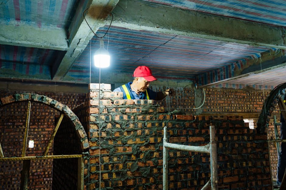
AAC — autoclaved aerated concrete — installs by a different rulebook than clay brick: dry-density typically 400-700 kg/m³, declared thermal conductivity 0.10-0.16 W/(m·K), and a thin-bed mortar joint of 2-3 mm instead of the 10 mm cement-sand bed used on dense masonry [S1]. The lower mass cuts dead load roughly one-third versus fired clay brick of equivalent wall area, but it also cuts the wall's compressive reserve, which is why most cracking callbacks trace back to movement joints, tie spacing, and the wet-trade schedule after laying.
This guide walks the install sequence a site engineer actually runs: substrate prep, first-course leveling, AAC block laying with thin-bed mortar, wall-to-column and lintel detailing, and the cure/dry-out protection window before plaster. Standards referenced below are the long-standing GB 11969 autoclaved aerated concrete test methods and the wall-quality acceptance codes that govern AAC wall construction in China, where the bulk of AAC production is concentrated [S1][S2].
Substrate and first course: the leveling course decides the wall
A AAC wall is only as plumb as its first course, and the first course is only as level as the slab or beam it sits on. Sweep the substrate, mark the wall centerline with a chalk line, and dampen the contact face — not soak it — so the first-course cement-sand bedding mortar (typically 1:3 mix, 15-20 mm thick) can hydrate without losing water into dry concrete. The leveling course exists because AAC is machined to ±1.5 mm height tolerance, but the structural slab beneath it is not, and trying to fix a 5-10 mm low spot with thin-bed mortar is a guaranteed crack initiator at the bed joint. [S1]
Set the corner blocks first, run a tight string line between them, and lay the run between corners before the bedding mortar loses workability. Check level across the full run with a 1 m spirit level; deviation greater than 2 mm across 1 m means rake out and re-bed, do not shim with thin-bed mortar [S1]. A wall that starts out of plane cannot be pulled back into plane by tightening joints — thin-bed mortar sets fast and has no slump reserve once the course is laid.
Thin-bed mortar: 2-3 mm joint is the whole point
Thin-bed AAC mortar is a factory-pre-blended polymer-modified cementitious adhesive, applied with a notched trowel that leaves 2-3 mm of material when the block is pressed home. Mix only the volume you can lay in the open time on the bag (typically 1-2 hours at 20°C); re-tempering by adding water after initial set destroys the polymer bond and gives you a sand-cement joint in disguise, which is exactly the joint the AAC system was designed to avoid [S1].
Butter the block head joints as well as the bed face; a head joint starved of mortar becomes a vertical crack waiting for shrinkage stress. After pressing each block, scrape the squeeze-out flush with the wall face rather than smearing it across the face — a smeared squeeze-out seals the surface and stops the plaster key from forming. If the wall will be plastered, leave a slightly recessed joint so the plaster can key across; if the wall will be left fair-faced, tool the joint flush before the mortar skins over.
Ties, movement joints, and the wall-to-column interface

An AAC wall does not carry vertical load the way a clay-brick wall does; the tie system does. L-shaped or trussed wall ties get bedded into the column at 600 mm vertical centres (or two courses of standard 600×200×100 mm block), embedded at least 75 mm into the mortar joint, and lapped at least 60 mm into the AAC bed joint. Skipping a tie row to "save time" is the single most common cause of partition-wall-to-column separation cracks that show up two heating seasons after handover. [S1]
Movement joints in AAC follow the structural-column grid at 6 m maximum spacing, with a 10-15 mm gap filled with compressible backer rod and flexible sealant — do not fill with mortar. Where the wall meets a dissimilar material (RC column, steel beam, window frame), leave a 10-15 mm separation and seal it; AAC moves with humidity and temperature differently than concrete or steel, and a rigid joint at that interface is a guaranteed crack. Bed-joint reinforcement — typically 4 mm galvanized steel wire or a mesh strip — runs every third course and at the head and sill of openings, and is what keeps shrinkage cracks from running the full wall height.
Openings, lintels, and embedments
Openings wider than 600 mm need a lintel; the typical site choice is a reinforced AAC lintel block or a steel angle (L 75×50×5 minimum for 1.2 m clear span in 100 mm wall), with 200 mm minimum bearing at each end. Openings narrower than 600 mm can carry through with bed-joint reinforcement wrapped around the head, but only if the surround is fully bedded and the reveal is notched back to the full wall thickness — partial-depth reveals crack at the corner under door slam loads. [S1]
Embedments — electrical conduit, water service pipes, chases for HVAC — must be cut with a wall chaser, not a hammer. Chase depth is limited to one-third of wall thickness on one face only, and the chase run is offset from the nearest bed joint by at least 50 mm; horizontal chases longer than 1 m in a 100 mm wall reduce the net section to the point that the wall acts as a beam rather than a partition. After the service is laid, patch the chase with thin-bed mortar in two passes, not one wet fill — a wet fill shrinks and pulls.
Curing, protection, and the plaster schedule
AAC must be protected from direct wetting and direct sun for the first 24-48 hours after laying; cover the top of the wall with a tarp or plastic sheet at end-of-shift so rain cannot pond in the unfilled cores and saturate the lower courses. Do not load the wall with plaster for at least 7 days — the block is dimensionally stable once autoclaved, but the mortar joint needs that window to reach design bond strength [S1].
When plastering does start, dampen the wall face (not saturate) and apply a polymer-modified cement render in two coats: a 5-8 mm scratch coat with the AAC surface left slightly rough to provide key, then an 8-12 mm finish coat after the scratch has cured 24 hours. Total render thickness is held to 15-20 mm; thicker renders slump on AAC and debond at the interface. Window and door reveals get fiberglass mesh bedded into the scratch coat at the corner, otherwise the reveal corner cracks within the first thermal cycle.
Field acceptance checks and the failure modes to refuse
Acceptance is a checklist the clerk of works runs before the wall is closed up. Items that fail the wall: bed-joint thickness outside 2-3 mm by visual or gauge; wall plane deviation greater than 4 mm over 3 m; missing or under-embedded ties at any course; chases deeper than one-third of wall thickness on a single face; mortar squeeze-out left smeared on the face in walls scheduled for plaster; movement joints missing at 6 m centres or filled rigidly [S1].
The four failure modes that dominate AAC callbacks — and that the above checks are designed to catch — are: (1) bed-joint cracking from a leveled-out first course, (2) wall-to-column separation from missing or wrongly spaced ties, (3) shrinkage cracks at openings from missing bed-joint reinforcement or wrong lintel bearing, and (4) plaster debond from a sealed face or wrong render thickness. Each of these is a workmanship defect, not a material defect; the AAC block itself is within spec on all four. When in doubt, re-lay the affected course rather than patch it — patch repairs on AAC walls do not age well, and the AAC block cost is small compared to the snagging cost two heating seasons later. For broader material-handling context on the equipment side of the supply chain, the force gauge selection logic for plant commissioning lines up well with the QA-density testing done on the finished block.
Spec-level background on the components involved: linear guide, and crossed roller guide.