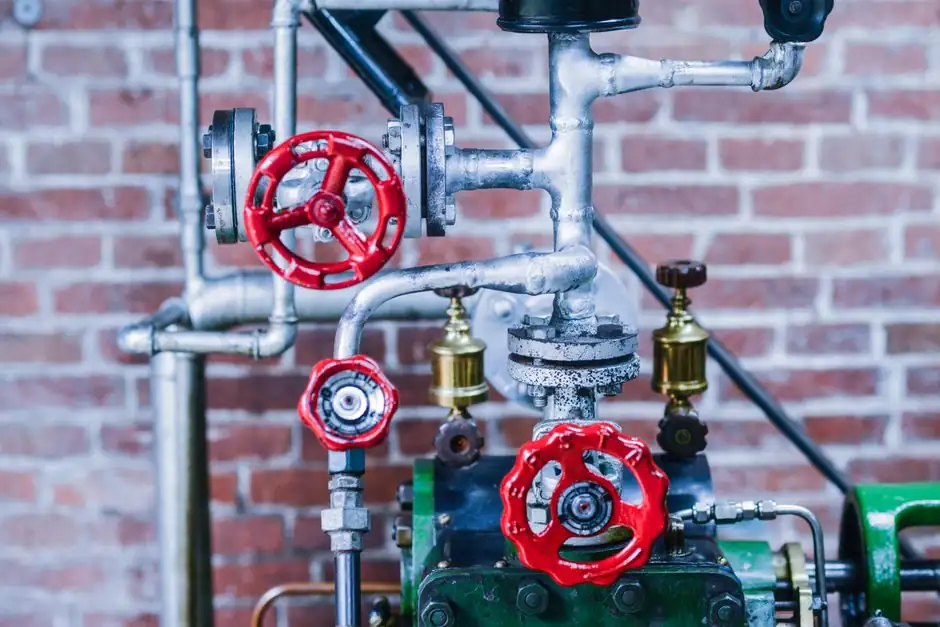
On loss of power or control signal, a precharged nitrogen-over-hydraulic accumulator releases stored fluid through a trip pilot valve into the hydraulic actuator, driving the valve to its safe position using only local stored energy, with no external input required [S1][S3].
For Emergency Shutdown (ESD) duty, the hydraulic cylinder is sized so that the energy available from the accumulator between the maximum system pressure (P2) and the minimum working pressure at end of stroke is greater than the work required to seat the valve under worst-case differential pressure [S2][S3].
Precharge Pressure and P1/P2 Operating Window
An accumulator is a pressure vessel with a membrane or piston confining an inert gas, normally nitrogen, on one side and hydraulic fluid on the other; when system pressure exceeds the nitrogen precharge, the gas compresses and fluid enters, and when system pressure drops the gas expands and forces fluid back out [S2]. The two reference points are P1 (system pressure at which the accumulator is empty, gas expanded back to precharge volume) and P2 (system pressure at which the accumulator is full, gas compressed to its minimum volume) [S2].
For fail-safe stroke design, the precharge is set below the minimum standby pressure of the actuator, typically 80-90% of that minimum, so the gas does not bottom out and lose delivery head before the stroke completes; circuits in production datasheets charge to 3,000 psi when only 2,000 psi of working pressure is required, deliberately over-pressurising to hold usable flow above the system minimum as pressure decays [S2].
Energy Delivery vs Spring-Return Backup
Two architectures compete on ESD valves: spring-return, where a pre-loaded mechanical spring drives the valve to its safe position when hydraulic pressure is lost, and accumulator-backed, where stored pressurised fluid performs the same function [S1]. Spring-return designs are mechanically simple and trigger the instant pressure decays, but they are limited to a single stroke and must be carefully matched to the valve geometry and torque profile [S1].
Accumulator-backed systems store significantly more energy than a single spring, which directly translates to longer strokes, larger valve bores, higher ΔP closure, or the ability to perform multiple backup operations from one reservoir [S1]. For a Class 900+ ESD ball valve on a high-pressure gas line, a spring typically cannot store enough energy to break the valve away from seat and traverse the full 90 degrees under full ΔP; a correctly sized bladder or piston accumulator can [S1][S3].
Accumulator Sizing for Worst-Case Stroke

Accumulator volume and precharge pressure together set the fail-safe stroke energy: V_available = V0 x ( (P2/P1)^(1/n) - (P2/P_min)^(1/n) ), where n is the polytropic index of the nitrogen charge (roughly 1.4 for adiabatic, 1.0 for isothermal slow discharge) and P_min is the lowest pressure at which the actuator can still develop enough force to move the valve [S3][S4]. The engineering practice is to size for worst-case conditions, including pressure drop across the trip valve, line losses, and leakage, not for the ideal no-loss case [S4].
Undersizing the accumulator produces partial closure, slow end-of-stroke velocity, or outright failure to seat against process pressure, which is the same failure mode as a broken spring, except the symptom appears only on the first real trip [S4]. Oversizing is cheaper than undersizing on ESD duty because the cost of a non-closure event is process downtime, regulatory exposure, and potential loss of containment [S3][S4].
Charging Circuit, Trip Valve, and Pressure Retention
The accumulator is held in a charged state by the system hydraulic pump through a check valve, with a pressure switch that unloads the pump when standby pressure is reached and re-starts it on decay [S2]. A normally-closed solenoid or pilot-operated trip valve sits between the accumulator and the actuator cap-end; on a trip signal, the solenoid vents, the trip valve opens, and stored fluid drives the piston [S1][S2].
Pressure retention is the silent failure mode. Internal or external leakage anywhere in the charging check valve, trip valve, or actuator seals bleeds the accumulator between proof tests, and a reservoir that was full at the last inspection can be at 60% charge when a real ESD fires [S4]. For this reason, accumulator-backed ESD circuits are specified with periodic pressure-decay surveillance, nitrogen precharge verification, and a documented Mean Time To Repair (MTTR) for the charging sub-system [S4].
Where Accumulator-Backed ESD Fits, and Where It Does Not
Accumulator fail-safe stroke is the right answer for NPS 24+ ball and gate valves on pipelines, Class 900+ shutdown valves in oil and gas, subsea or buried installations where routine maintenance access is limited, and remote stations where the valve must work first time without external power [S3]. It is also the default in Safety Instrumented Function (SIF) loops where the ESD valve is the last line of defence and the process Safety Integrity Level (SIL) rating is set by valve closure reliability [S1].
It is the wrong answer where system simplicity, low maintenance burden, or a clean-room environment dominates, because the hydraulic charging circuit, accumulator, trip block, and fluid management add real complexity compared with a pneumatic spring-return or all-electric actuator [S3][S4]. The trade-off is well known: an accumulator buys you long stroke and high force under stored energy, but it also buys you a nitrogen precharge to monitor, a charging check valve to test, and a hydraulic fluid cleanliness regime to maintain [S2][S3].
Comparison: Spring-Return vs Accumulator-Backed Fail-Safe
Four decision criteria separate the two architectures in real spec work: stored energy per unit volume, single vs multiple stroke capability, sensitivity to leakage, and maintenance discipline. Spring-return wins on simplicity and on zero dependence on fluid cleanliness, but loses on multi-stroke capability and on absolute stored energy for large-bore high-ΔP valves. Accumulator-backed wins on energy density and on the ability to re-stroke after a partial closure or after a partial leak-down, but loses on the need to verify nitrogen precharge, monitor pressure decay, and maintain fluid cleanliness to ISO 4406 levels. [S3]
In practice, the choice is driven by valve size and SIL target, not by preference: above NPS 16 or above Class 600, accumulator-backed is the default because a spring package capable of moving the valve under full ΔP becomes physically and economically impractical; below NPS 6, spring-return is common because the spring is small enough to package and the SIL budget is usually met by other means [S1][S3].
Hydraulic Motion Control and Adjacent System Choices
The same fail-safe logic shows up in other process-control hardware where stored mechanical or fluid energy has to back up an electrical signal. A positioner that loses its 4-20 mA or pneumatic supply has to default to a known state, and a smart vs analog pneumatic positioner spec-by-spec breakdown covers the same fail-safe pattern on the control side, not the actuator side. Likewise, the shaft-hub power-transmission question on a valve stem nut often comes down to the same stored-energy trade-off analysed in a locking assembly vs keyway friction vs shear comparison, where the failure mode under impact load is the design driver. [S4]
Trackable signals for the next design review: (1) the SIL target of the ESD SIF and the proportion of overall PFD_avg that the actuator and accumulator subsystem is allowed to consume, typically 30-50% in a well-balanced loop; (2) the documented proof-test interval for the accumulator nitrogen precharge and for the trip pilot valve, which dominates the dangerous undetected failure rate of the stored-energy sub-system [S4].