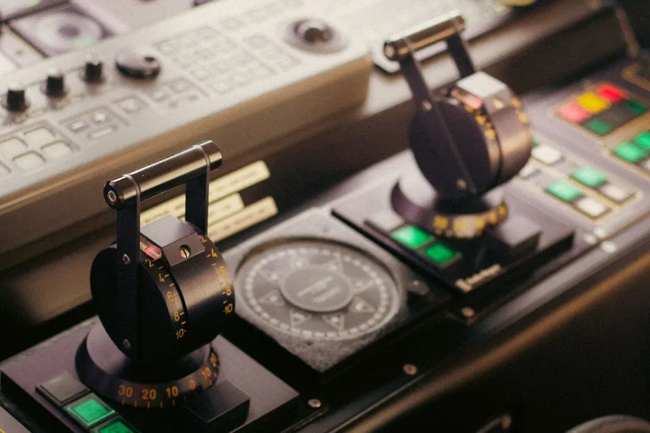
A weight and lever swing check valve adds an external mass on a lever arm to overcome the slow gravity-only closure of a 80 to 90 degree disc swing, with the lever torque and weight position setting the closing rate [S1][S2].
Closing speed is governed by a simple mechanical trade-off: the weight position along the lever changes the torque applied to the disc as flow decays, which determines how fast the disc traverses its arc and seats against the body [S3][S4].
Lever Arm Mechanics and Disc Stroke Geometry
A conventional swing check valve disc sweeps an 80 to 90 degree arc from fully open to fully seated, and gravity acting on the disc alone is too slow to prevent reverse velocity from building in the piping [S1]. Adding a weight on a lever arm external to the body magnifies the closing torque by the lever ratio, so even a modest mass produces enough rotational force to drive the disc through its travel before the reverse flow peak arrives [S2][S7]. The lever typically pivots on the same hinge pin as the disc, so its angular motion tracks the disc 1:1, and the torque at the disc equals the weight force times its radial distance from the pivot [S3].
Two geometric variables therefore define closing performance: the lever length L, and the weight position a along that lever. Closing torque scales as W times a, so doubling either roughly doubles the available closing moment, while disc inertia and seat friction stay roughly constant for a given valve size [S7]. Engineers adjust a in the field to tune closure rate, with the inner position giving a snappy seat and the outer position giving a cushioned arrival [S3][S4].
Weight Position Versus Closing Speed and Water Hammer
Positioning the weight closer to the hinge pin delivers the fastest closing time, because the shorter moment arm concentrates force into quicker angular acceleration of the disc and lever assembly [S3]. This mode is typically selected where pump reverse flow must be cut off aggressively, for example on centrifugal discharge lines where any backflow through the impeller is unacceptable [S1]. The trade-off is a harder seat impact, which raises peak contact force against the seat ring and increases seat wear over thousands of cycles [S7].
Moving the weight outward along the lever reduces the closing torque, lengthens the closing time, and lowers the disc velocity at the moment of contact, which directly limits the pressure surge that drives water hammer [S4][S8]. Industry guidance for check valve selection in municipal water and wastewater service ties this soft-close behaviour to the 5 to 15 ft/s flow velocity range most manufacturers specify as the stable operating band for a self-aligning disc [S2]. When closing is too slow, however, the disc can hang in mid-stroke during flow reversal and then be slammed by the returning fluid column, defeating the purpose of the lever [S7].
Comparison of Closure Strategies for Swing Check Valves

Four practical closure strategies are commonly compared against the same pumping duty, with closing torque, slam risk, maintenance load, and rag-handling capability as the main decision criteria: [S2]
1. Gravity-only (no lever): zero added closing torque, no external snagging points, but high slam risk on long pump discharge lines because the 80 to 90 degree stroke completes after the reverse velocity peak arrives [S1][S2].
2. Weight and lever, weight near hinge: maximum closing torque from the lever ratio, fast seat, higher seat impact force, and the lever assembly adds external parts that can snag rag in wastewater service [S3][S1].
3. Weight and lever, weight at outer end: reduced closing torque, cushioned seat, lower water hammer peak, same snagging exposure, suited to clean-water transmission where surge control is the priority [S4][S8].
4. Resilient hinge check valve: no external lever or weight, internal spring or elastomer hinge controls the closing rate, fewer snag points, and EN 12334 conformity is common for control valve style weighted swing check valves used in waterworks [S1][S8].
Failure Modes, Sourcing Standards, and Field Adjustments
The dominant failure mode in a swing check valve with external lever is rag or debris fouling the lever, hinge, or disc pivot, which prevents full closure and leaves the disc hanging in the flow [S1]. On wastewater duty, the lever and weight assembly alone can contribute up to roughly a dozen individual components that protrude into the flow path, and operators commonly retrofit a shroud or switch to a resilient-hinge body when rag build-up forces frequent lift-station maintenance [S1]. A second failure mode is seat erosion, which accelerates when the weight sits too close to the hinge and closing energy is dissipated in a single hard impact rather than over a cushioned arc [S7].
Product sourcing for weighted swing check valves used in waterworks commonly references EN 12334 for the valve body and face-to-face dimensions, with AWWA C508 covering equivalent ductile-iron flanged designs such as the SCI Series 22FCW [S8][S6]. The ASME conference paper ICONE22-30879 documents the lever, weight, and jaw-stops arrangement on a representative nuclear-class swing check, confirming that jaw stops on the shaft limit the open and closed travel so the lever cannot over-rotate into the bonnet [S5]. Field adjustment of the weight along the lever is the primary tuning action, and installers are advised to start with the weight in the mid-lever position and move inward in small steps until a soft but positive seat is heard at pump shut-off [S3][S4].
Selection Cues and Verification Signals
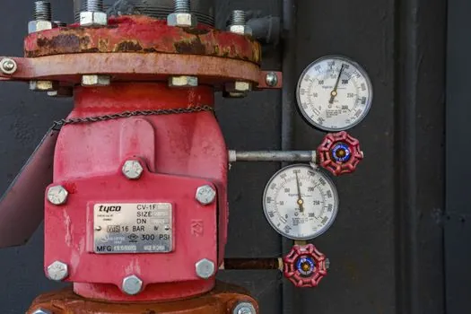
Specifying a weight and lever check valve over a gravity-only swing check or a resilient-hinge body is the right call when the duty cycle is clean water, the discharge line is long enough for surge pressure to matter, and the operator can tolerate routine external inspection. For raw sewage, slurry, or fibrous media, a resilient-hinge check valve removes the snag point entirely and is now the more common selection in new lift-station builds [S1]. Where a weighted swing is retained for EN 12334 compliance on a transmission main, expect a lever and weight assembly such as the SCI Series 22FCW with ductile-iron body and flanged ends, sized to the line, and tuned so the disc seats within the last 10 to 20 percent of the reverse-flow event [S6][S2].
Next step for a specifier: confirm the pump shut-off surge pressure on the actual discharge line, then size the lever weight so the disc seat velocity stays under roughly 1 m/s at impact, which is the typical threshold for keeping water hammer peaks within the valve body rating. Trackable signal to watch is whether the supplier publishes an EN 12334 test certificate for the specific body and lever assembly shipped, rather than only for the bare body.
Background reading: Ball Spline Preload Classes: Z0, Z1, Z2 and How to Pick the Right One.