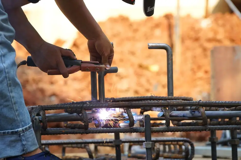
For ACI 318-19 compliance, a mechanical rebar coupler must develop at least 125% of the specified yield strength (fy) of the parent bar under monotonic tension testing, with Type 1 splices matching fy and Type 2 splices carrying the full 1.25·fy load [S2][S3][S4].
The 125% threshold has been the US qualification benchmark since the ACI 318-95 cycle and remains the controlling rule under ACI 318-19 clause 25.5.7.1, with ASTM A370 supplying the tensile-test protocol and ACI 318 supplying the acceptance pass/fail line [S1][S2][S6].
What the 125% fy rule actually measures
The 1.25·fy criterion is a strength ratio, not an absolute stress: the coupler assembly, parent bar, and any upset or threaded section together have to carry 1.25 times fy of the bar grade before yielding or failing [S2][S3]. On a Grade 60 (fy = 420 MPa) #8 (25M) bar, that translates to roughly 525 MPa of assembly-level stress at the acceptance point, with the bar's own ultimate tensile strength typically running 25% to 40% above fy depending on ASTM A615 grade [S6].
For nuclear safety-related work, the acceptance window is set even higher: ASME Section III Division 2 paragraph CC-4333, invoked through NRC Regulatory Guide 1.136, requires splices in concrete containments to develop the full ultimate tensile strength of the parent bar, and qualification is documented through monotonic and cyclic test programs run on production-procedure couplers [S1].
Two splice classes, two test thresholds
ACI 318-19 splits mechanical splices into Type 1 and Type 2, and the tensile test threshold follows that split. Type 1 splices need to develop at least 1.25·fy, the same headline number that applies to the generic "mechanical splice" rule, while Type 2 splices must develop the specified tensile strength of the parent bar and are required where the splice is located in a plastic hinge zone or in elements resisting seismic load [S2][S6].
In practice, most specifiers call out Type 2 by default because Type 2 is unrestricted by location, while Type 1 carries limitations on where in the frame it can be used. The monotonic tension test (a single, slow pull to failure) is the workhorse qualification for both classes; cyclic and slip tests are layered on for seismic and nuclear work but do not replace the monotonic acceptance result [S1][S6].
How the monotonic tensile test is run
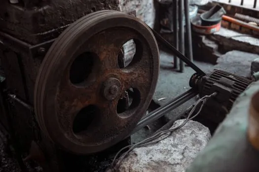
Specimens are full splice assemblies: parent bar, coupler, and any upset or threaded transition on each side, with the coupler centered in the gauge. Load is increased monotonically (no cycling, no unloading) to the acceptance threshold and held long enough to confirm the assembly holds 1.25·fy without slip, necking, or fracture, then typically continued to ultimate to characterise the failure mode [S1][S6].
Instrumentation is straightforward, but the pass criteria are tight: total slip across the splice is usually capped at values on the order of 0.1 to 0.3 mm at the 1.25·fy hold (the exact number is set by the project specification, not the code), and the failure mode should be bar yield or bar fracture outside the coupler, not coupler rupture or thread stripping [S1][S3][S6]. For a baseline on machine selection, see the tensile testing machine reference and the broader electronic test overview.
Who the 125% rule is for, and who it is not
The 1.25·fy rule is mandatory for any US project citing ACI 318-19 for structural concrete, including high-rise columns, shear walls, mat foundations, bridge piers, and any member where the splice sits in a region of calculated tension [S2][S4][S6]. It also covers the nuclear-power safety-related case through ASME III-2 CC-4333, where the requirement is full ultimate rather than 1.25·fy [S1].
It is not the right yardstick for projects outside the ACI code family, because the threshold differs. IS 16172 in India also sets a 1.25·fy acceptance line for full-strength couplers, but runs the test on metric TMT bars to IS 1786 and uses different sample sizes; IS 456 clause 26.2.5.2 carries its own comparison language against lap splices [S2][S5]. The ACI 318 number should not be quoted as a universal rule, and the rebar coupler reference page describes the wider splice family.
Choosing the right coupler to clear 1.25·fy
Three coupler families clear the 1.25·fy line in routine production work, and they trade off differently on installation speed, bar-prep, and field tolerance. Cold-swaged sleeves rely on a hydraulic press forcing the sleeve wall into the bar deformations, so bar-end prep is minimal but the press is capital-intensive [S2]. Threaded couplers, including parallel-thread and tapered-thread systems, are fast on site and easy to inspect, but require upset or cut-thread bar ends and a torque-controlled installation [S2][S5]. Set-screw (lock-shear bolt) couplers, the newest of the three, install with an impact wrench until the bolt heads shear off, embedding serrated strips into both bar and sleeve wall, and are popular for retrofits where torque verification is awkward [S2].
On selection criteria, swaged couplers are common in nuclear and heavy-civil work where bar-prep is done in a shop, threaded couplers dominate high-rise and precast where speed and inspection traceability matter, and set-screw couplers are the default for field retrofits and congested splices. All three pass the same ACI 318-19 tension test, but the qualification paperwork, sample size, and re-test triggers differ, so a coupler that cleared 1.25·fy on a #8 bar does not automatically qualify a #14 bar without a separate qualification lot. The rebar and rebar bender references cover the parent bar side of the workflow.
Failure modes and qualification pitfalls
The disqualifying outcomes in a 1.25·fy monotonic test are: coupler body fracture, thread strip-out, bar fracture inside the coupler (as opposed to outside), or measurable slip that exceeds the project-set limit before the 1.25·fy hold [S1][S3][S6]. The most common cause of a failed lot is not bad couplers but inconsistent bar-end prep, which is why manufacturers and contractors qualify a specific bar-prep procedure (cutoff, saw, upset, thread roll) alongside the coupler itself [S2][S5].
Sample size, re-test rules, and acceptance criteria are not set by ACI 318 directly; they live in the project specification, in ICC-ES AC133, or in the manufacturer's own qualification report, so two projects citing ACI 318-19 can run the same monotonic test but accept the result on different rules [S2][S6]. Always read the project spec for the slip cap and the re-test trigger, not just the code clause.
Related reading and the next step
For a structural-engineering view of why the 125% margin exists in seismic detailing, see the silica fume dosage in high-strength concrete working-window reference, which covers the concrete-side ductility assumptions that complement a Type 2 splice. For pre-qualification paperwork and sample-size planning, the calibration management software and connected instruments piece covers the load-cell and extensometer traceability that an audit will ask for. [S5]
Two trackable signals to watch: ICC-ES AC133 acceptance criteria revisions, which drive the de-facto US re-qualification rule for new coupler families, and ASTM A370 revision work, which sets the load-rate and strain-rate protocol behind every monotonic tension test. Either a new AC133 edition or an A370 revision will change the paperwork even when the 1.25·fy number itself stays put.