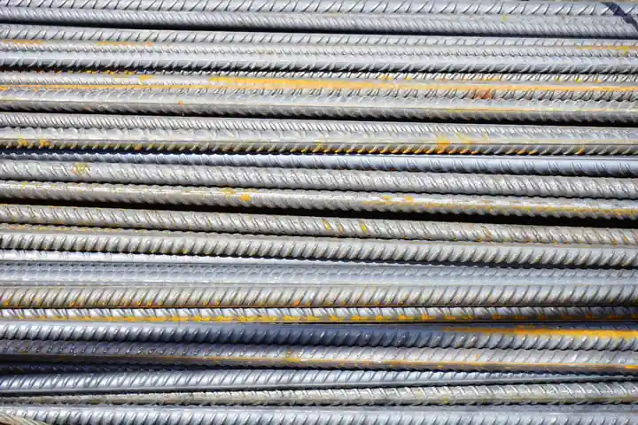
A swaged compression sleeve is cold-forged onto the rebar with a hydraulic press and special dies, with no threading of the bar end required [S5]. A threaded rebar coupler is a short steel sleeve with internal threads that mechanically joins two reinforcing bars end-to-end, transferring load through thread engagement rather than through the surrounding concrete [S3].
Both systems fall under the ACI 318:19 mechanical-splice category (clause 25.5.7.1) and must typically deliver 125% greater capacity than a lap splice of the same bar [S1]. Selection between the two is driven by bar size, project schedule, equipment access, and seismic slip tolerance rather than by raw strength, since both classes are routinely engineered to bar-break performance on ASTM A615 Grade 60 stock [S3][S5].
Swaged Compression Sleeve: How It Works and Where It Fits
Swaged couplers use a hydraulic swaging press with special dies to deform the sleeve around the ends of the spliced reinforcing bars, locking the bar ribs into the sleeve wall [S5]. The cold-swaged coupling sleeve is the standard CRSI-recognised method when bar-end preparation is impractical, because the press does the gripping work without threads, taper, or grout [S5].
The embedment length is short: only two bar diameters (2db) per bar side can be sufficient to transfer tension load when the sleeve is properly pressed [S1]. Cold swaged couplers require a hydraulic press to deform the sleeve onto the rebar, and installation is a one-person operation on vertical column bars where a thread-cutting machine would be hard to position [S2][S4]. For these reasons, swaged sleeves are common on #8 (25 mm) through #14 (43 mm) column verticals and on bridge piers where speed and a slim coupler OD matter more than torque traceability.
For sizing reference, the outer diameter and length of swaged sleeves track closely with the bar diameter in published charts, as laid out in the Rebar Coupler OD and Length Chart by Bar Size (2026 Spec Guide). The main trade-off is field verification: a swaged joint is checked by die pressure and a go/no-go gauge, not by a torque wrench value, so QA documentation has to be tied to the press calibration log rather than to a per-joint number.
Threaded Coupler: Upset, Non-Upset, and Taper Thread Options
Threaded couplers use internal threads that engage matching external threads on each bar end, creating a continuous steel-to-steel load path with no dependence on concrete bond [S3]. Two primary threading designs dominate: parallel threads on square-cut or upset ends, and taper threads that allow hand-spin installation and final lock-up with a few wrench turns [S3].
Upset straight thread couplers enlarge the bar end before cutting threads, so the threaded section retains a cross-sectional area greater than the parent bar; this is the CRSI-recommended approach because thread cutting otherwise reduces net area and force some manufacturers to step up one bar size to compensate [S5]. Non-upset straight thread couplers accept the area loss and rely on higher-strength bar stock to recover capacity, while the threaded-rebar-deformed-bar variant uses specially rolled thread-like deformations over the full bar length and is locked with a torqued lock nut rather than a cut thread [S5].
Threaded couplers are widely specified for seismic Type 2 connections because slip is governed by thread tolerance, which can be held to a known millimetre value across a production lot. The numeric basis for that slip limit is detailed in Type 2 Rebar Coupler Slip Tolerance: Spec Numbers and Code Basis, and the seismic material context (the 1.25 TS/YS ratio demanded for Grade E rebar) is covered in Seismic Grade E Rebar 1.25 TS/YS Ratio: Specs, Logic, and Material Limits.
Decision Matrix: Swaged vs Threaded Across Four Criteria
Comparing the two on the criteria that drive rebar coupler specification: bar-end preparation, field equipment, seismic slip control, and installation rate. Swaged couplers need no bar-end prep at all, the press is the only special tool, slip is controlled by die geometry and is harder to inspect per joint, and a trained operator can complete a splice in roughly 30 to 60 seconds per end on typical column verticals [S4][S5]. Threaded couplers require either upset forging or precision thread cutting on every bar end, need only a torque wrench, hold slip to a tight thread-tolerance band suitable for Type 2 seismic, and install in one to two minutes per end with a calibrated torque value that doubles as the QA record [S3][S5].
For projects that demand seismic ductility, threads win because thread tolerance is a controlled machine parameter; for projects driven by tonnage and schedule, swaging wins because the press cycle is faster and there is no thread-cutting queue in the rebar fabrication shop. Threaded systems are approved under ACI 318, Eurocode 2, AASHTO, and IBC, and are stocked from #4 (12 mm) through #18 (57 mm) in mainstream product lines [S3]. Swaged systems are likewise covered under the same ACI 318 mechanical-splice provisions when the 125% capacity threshold is met, but bar-size range is typically #4 through #14 in standard press-die sets [S4][S5].
On cost, the swaged sleeve itself is cheaper per unit, but the hydraulic press and dies represent a capital cost that has to be amortised across the splice count; the threaded sleeve is more expensive per unit, but bar-end prep can be done on a standard lathe and installation needs only a torque wrench, so the per-joint labour can be lower on small-to-medium projects [S1][S3].
Selection Criteria: Bar Size, Seismic Class, and Site Constraints
For #4 (12 mm) through #7 (22 mm) bars in light-commercial slabs and walls, threaded couplers are usually the default because the bar end can be threaded on a shop lathe with standard tooling and the torque value is easy to record in the QA log. For #8 (25 mm) and larger column verticals, swaged couplers become attractive because the press cycle is short and the threaded alternative would require either an upset forging operation on every bar or a step-up to the next bar size to recover the area lost to thread cutting [S5].
Seismic framing and column-splice zones typically call for Type 2 couplers, which in practice points to threaded systems with a documented slip tolerance (commonly under 0.25 mm at service load) and a verified bar-break failure mode outside the coupler body [S3]. For non-seismic compression members, where lap splices would otherwise be acceptable, a swaged compression sleeve or the grouted-sleeve alternative (for precast) is often the cheapest way to clear the congestion that the 50% longer lap required for epoxy-coated bars would otherwise force into the joint [S1][S4].
Site access matters: a hydraulic swaging press needs a stable footing and a clear axis for the die, which is fine on an open deck but awkward in a tight basement column cage, where a torque wrench on a threaded coupler is easier to manoeuvre. Conversely, on a precast yard with a fixed press station, the swaged path is hard to beat for throughput.
Failure Modes, Limits, and Field Pitfalls
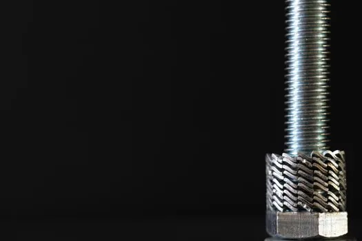
The dominant swaged-sleeve failure modes are under-pressed sleeves (die pressure too low, bar pulls out), over-pressed sleeves (sleeve cracks or bar ribs sheared off), and sleeve eccentricity when the bars are not centred, which creates a bending component in what should be a pure axial splice [S1][S5]. Field QA has to verify the press gauge, the die set, and the sleeve OD after pressing, and any sleeve that is not fully pressed has to be cut out and replaced; there is no torque value to re-check.
The dominant threaded-coupler failure modes are cross-threading on installation (which destroys the joint), under-torqued lock nuts on the thread-deformed-bar variant, and thread damage from rebar storage corrosion or jobsite handling. Bar-break performance, where the parent bar fails outside the coupler body before the threads strip, is the target for both systems and is achievable on ASTM A615 Grade 60 stock with either upset-end parallel threads or properly made taper threads [S3][S5].
Codes such as ACI 318:19, clause 25.5.7.1, require that mechanical splices deliver higher performance than lap splices, typically 125% greater capacity, and this threshold must be met by the as-installed system, not just by the catalogue rating [S1]. For seismic applications, ACI 318 also requires that the splice develop the specified tensile strength of the bar, which is why Type 2 threaded systems are common in high-seismic zones and why the 1.25 TS/YS material ratio on Grade E rebar interacts with the coupler choice rather than being independent of it [S3].
When NOT to Use Each Type
Do not use a swaged compression sleeve where the spec calls for a Type 2 seismic splice with verifiable torque or slip documentation, because the swaged joint's slip is governed by die geometry and bar-surface variability, not by a per-joint torque number. Do not use a standard threaded coupler on bars that have not been upset and where the bar size cannot be stepped up, because the net-area loss from thread cutting can drop the threaded section below the parent-bar capacity [S5]. Do not use a swaged sleeve on bars that have been heavily corroded or had their ribs worn smooth, because the cold-forged grip depends on the ribs embedding into the sleeve wall [S1].
Do not use a parallel-thread non-upset system on a critical seismic column splice if the bar supplier cannot certify the tensile-to-yield ratio, because the area loss from thread cutting has to be recovered somewhere in the material property budget. Do not use either system as a compression-only substitute for a properly designed lap splice without checking the code minimum, because some specifications permit compression-only connections with a lighter-duty sleeve (e.g. the Speed Sleeve) that would be non-compliant in a tension zone [S2].
Sourcing, Standards, and What to Verify on a Submittal

For a swaged system, the submittal should include the press model and die set, the calibrated die pressure per bar size, the manufacturer's ICC-ES or equivalent evaluation report, and a sample of the QA form the crew will use to record each joint. For a threaded system, the submittal should include the bar-end prep method (upset or non-upset), the thread standard (typically ASME B1.1 or the coupler maker's proprietary spec), the torque table per bar size and grade, and the test report demonstrating 125% of specified yield and bar-break failure mode [S1][S3][S5].
For a broader cross-industry comparison of mechanical-splice selection logic and how similar trade-offs show up in other building-product decisions, see the Self-Adhered vs Hot-Applied Sheet Membranes: External Waterproofing Decision reference, which uses the same criteria-based structure. Code references to lock in the submittal are ACI 318:19 clause 25.5.7.1 for the 125% capacity threshold, and AWS D1.4/D1.4M only if welded couplers or welded lap splices are also part of the package [S1][S5].
The decision is rarely either/or on a large project: a single bridge or high-rise will typically run swaged sleeves on the column verticals, threaded Type 2 sleeves on the seismic column splices and beam-column joints, and either grouted sleeves or headed-bar terminations at the precast interfaces. Specifying both is normal, as long as the QA paperwork keeps the two systems cleanly separated. Trackable signals to watch over the next revision cycle are any updates to the ICC-ES acceptance criteria for cold-swaged couplers on #18 (57 mm) bar, and any tightening of the ACI 318 slip-tolerance language for Type 2 mechanical splices in high-seismic regions.
For the relevant spec sheets and selection criteria, see rebar coupler, shot sleeve, and rebar.