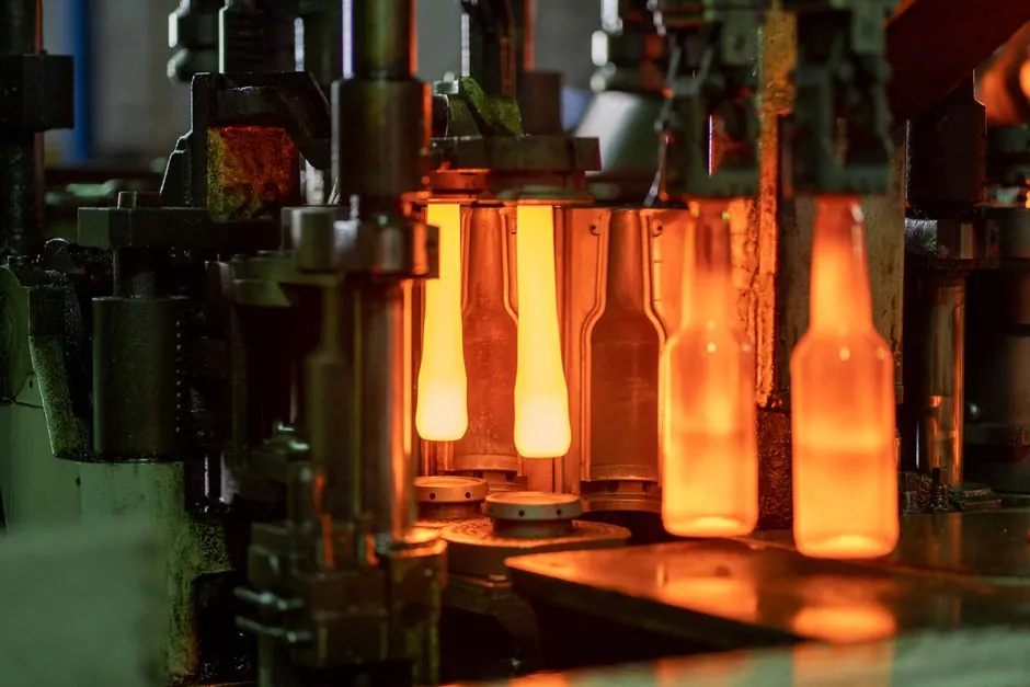
During high-pressure aluminum die casting, the die surface temperature can climb above 1000F (538C) at fill and then collapse to below 500F (260C) during die spray, a single-shot swing of more than 500F that drives most of the dimensional drift seen on the coordinate measuring machine [S1].
Process data from production cells puts practical mold temperature control for aluminum die casting in the 200-280C band, with a tight control window of plus or minus 10C cited as the primary lever for repeatable dimensions in high-pressure die casting [S4][S5].
Heat Flow Fundamentals Behind Shrinkage
Molten aluminum at roughly 690C contacts H13 tool steel pre-heated near 250C and transfers heat at peak rates above 5-8 MW per square meter in the first 0.5 seconds after injection, with about 60-65% of the shot's total heat leaving through the mold and the remainder through the shot sleeve and spray [S5].
A380 solidifies with about 6.7% volumetric shrinkage from liquidus to room temperature, and the majority of that contraction happens above 500C while the casting skin is still weak, so any 15-20C surface-temperature variation across the cavity creates a non-uniform solidification front [S5]. A zone held 20C hotter delays local solidification by 0.3-0.6 seconds, which adds roughly 0.03-0.05% extra shrinkage in that region once the part cools to 80C at trim [S5].
Operating Windows by Alloy and Wall Thickness
Alloys 226, 380, and 383 typically run with a cavity surface temperature of 180-320C: thin walls under 2.5mm need the upper half of the range to fill, while structural sections above 6mm are usually held at 180-240C to extract heat quickly and limit gas porosity [S5]. Magnesium AZ91D and AM60 sit in a 240-320C window, and zinc programs run cooler still, so a single tempering loop rarely covers all three [S5].
Standard mold temperature control units in service today cover process temperatures from 0F (-18C) up to 550F (288C), spanning both hot-chamber and cold-chamber die casting cells, and oil heat-transfer fluids rated to 360C are the recommended medium for the upper half of the aluminum window [S2][S3]. For more on cavity and die construction, see the aluminum die casting machine overview.
Conventional Cooling Layouts and Their Limits

Cooling water circuits and hot oil or hot water circuits are commonly run in parallel on the same die, with water routed through high-temperature zones such as thick casting sections and cores, and oil routed to areas where temperature uniformity matters more than peak heat removal [S1][S2]. In one documented 420 by 280mm AlSi9Cu3 instrument-panel bezel, the as-built cavity had a 78C delta between center and corners, and part length varied by plus or minus 0.19mm; adding two 10mm oil circuits in the cold corners cut the maximum delta to 11C and trimmed length variation to plus or minus 0.026mm [S5].
Cycle time is itself a thermal-control variable, since a change of just a few seconds shifts the die temperature at fill and can flip a good shot into a defect regime, and each additional second of die spray pulls further heat out of the steel [S1]. Pre-heating the die to the operating window before molten metal arrives reduces thermal shock at start-up, which is one of the documented drivers of premature tool failure in die casting dimensional capability practice [S2].
Modern Approaches: TCUs, Infrared Mapping, and Closed-Loop Control
Selecting a temperature control unit depends on the die's cooling-channel design: the channels must be sized for fast circulation with minimal pressure loss, the unit must be powerful enough to regulate and remove heat at the design duty, and the heat-transfer fluid must match the temperature band, with oil favored for the upper aluminum window because of its better high-temperature heat-transfer stability [S2].
Infrared imaging cameras are now standard tools for visualizing temperature variation across the die surface, and modern closed-loop control with thermocouples in the cooling channels can hold a plus or minus 10C band on cavity surface, which the supplier literature identifies as the working threshold for dimensional repeatability in high-pressure die casting [S1][S5]. For a deeper look at how die-life expectations interact with thermal cycling, see the aluminum die casting die life reference and the H-13 hardness and thermal fatigue guide.
Decision Matrix: Water, Oil, or Combined Circuits
Process engineers building a new die typically choose between three cooling-loop strategies, each with clear trade-offs in heat-removal rate, surface-temperature uniformity, and operating cost. The table below lines them up against the four criteria that come up most often on process reviews. [S5]
Water-only circuits deliver the highest peak heat flux and the lowest fluid cost, but they struggle to hold a uniform plus or minus 10C band above 180C and they risk localized boiling near hot cores [S1][S2]. Oil-only circuits, using a mineral fluid rated to 360C, hold tighter surface uniformity across the 200-280C aluminum window and are kinder to the H13 substrate, at the price of lower peak heat removal and higher pumping cost [S2]. Combined water-and-oil circuits, with water through thick sections and oil through cosmetic or thin-wall zones, are the workhorse layout in high-mix cells and are the configuration behind the 78C to 11C delta reduction documented on the AlSi9Cu3 bezel [S5].
Sensor Placement, Limits, and Failure Modes
Reliable closed-loop control requires a thermocouple seated about 4mm under the cavity surface, since that is the layer whose temperature actually moves 25-40C during a single cycle even when the bulk machine parameters look steady [S5]. Die-spray volume and duration are the most easily disturbed inputs, and once the die is at operating temperature both must be held constant shot to shot or the next die-temperature excursion is already on its way [S1].
The known failure modes map cleanly to temperature drift: cold shuts and misruns when the mold runs below 200C, longer cycles and accelerated solder or washout when it climbs above 280C, and a fire-crack onset pattern in H13 dies that is delayed by reducing peak surface temperature, which is the main reason oil circuits are favored on cosmetic surfaces even where water would remove heat faster [S2][S4]. Die-spray lubricants and release-agent selection also interact with the thermal-control story and are covered in the die coating reference.
Selection Criteria: When Tight Control Pays Off, and When It Does Not
Hold tight plus or minus 10C mold-temperature control when the part is a structural or safety-critical aluminum casting, when flatness or length tolerances sit below plus or minus 0.05mm, or when the cell is running thin walls under 2.5mm that cannot tolerate premature skin formation [S4][S5]. Relax the control band on heavy-section structural castings above 6mm where faster heat extraction actually improves mechanical properties, and on cosmetic-only parts where a downstream machining or deflashing operation can absorb the dimensional noise [S5].
For plants evaluating a vacuum die casting machine upgrade specifically to reduce gas porosity, note that tighter temperature control and vacuum-assist are complementary rather than competing, since both attack different defect families. Likewise, gravity die casting machine cells for low-volume structural parts usually run a wider temperature band than high-pressure cells because cycle time is not the binding constraint. Magnesium programs, run on a magnesium die casting machine, need the upper half of the 240-320C window because of the alloy's lower latent heat, and zinc cells on a zinc die casting machine typically run cooler than either.
Two trackable signals for the next planning cycle: infrared-mapping audits on at least one production die per quarter to catch drift in plus or minus 10C band compliance, and a die-spray log tied to the same CMM trend chart so any temperature excursion in the 4mm thermocouple has a documented cause. Both are repeatable engineering practices already in use at production die-casting suppliers cited in the current supplier literature [S3][S5].