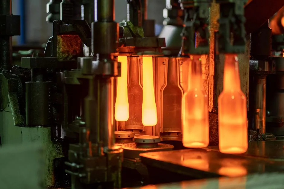
Polymer and metal additive manufacturing now spans the full mold-and-die stack, from SLS PA3200GF polymer inserts to SLM maraging 300 steel tooling, with the 84.2% cost reduction reported for SLS PA3200GF versus machined steel anchoring the economic case [S1][S3].
Selection is driven by four inputs: injected polymer grade, annual shot count, cavity surface pressure and required surface roughness, with material-process pairing driving both mold life and part cost per shot [S2][S3].
Material Families Used in AM Tooling
Four material families dominate mold-and-die AM: SLS polyamides (PA 3200 GF, PA12, PA11), photopolymer resins for DLP/SLA (digital ABS equivalents, HT resin, PA50Al blends), thermoplastic pellets for Material Jetting/FFF, and metal powders for SLM/DMLS (maraging 300, 17-4 PH, H13 tool steel, copper-alloy conformal-cooling inserts) [S1][S2][S5].
Highest flexural modulus in the published polymer-mold study went to HT resin, PA50Al blend and ABS-class resins, which is why they are favored for injection tooling cavities rather than cosmetic shells [S1]. For high-pressure or high-temperature plastics such as glass-filled PA66 or PC, maraging 300 SLM inserts and 17-4 PH SLM cores are the standard process pairing, with conformal cooling channels routed directly into the build to cut cycle time versus drilled-steel lines [S3][S5].
Selection Criteria by Production Volume
Production volume is the first cut, and the 10,000-part threshold is the widely cited break-even between additive and conventional steel tooling; below 10,000 parts the per-part cost of AM is lower, above it conventional injection tooling wins on cycle-time amortization [S4].
Inside that envelope, the literature converges on this banding: 1 to 500 parts uses SLS PA12 or DLP digital ABS for prototype and bridge tooling; 500 to 5,000 parts steps up to SLS PA3200GF glass-filled nylon or MJF PA12 with metal-insert reinforcements; 5,000 to 50,000 parts shifts to SLM maraging 300 or 17-4 PH stainless cavities, often with conformal cooling; above 50,000 parts, machined or powder-metal H13 steel is still the default, with AM reserved for the cooling channels only [S1][S3][S4][S5]. A separate strand reviews low-volume metal casting, where sand casting mold and casting mold workflows are themselves being augmented by binder-jetted sand patterns, so the same selection logic cascades into foundry tooling.
Process-Material Matching for Cavity Pressure
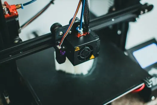
Cavity pressure and injection temperature dictate which process-material pairing survives; commodity polyolefines at 600 to 800 bar injection pressure run cleanly in SLS PA3200GF or DLP HT resin, while glass-filled engineering polymers above 240 °C melt temperature force SLM 17-4 PH or maraging 300 steel inserts with a copper-alloy conformal-cooling core [S3][S5].
The published comparison lines up cleanly on three criteria: surface roughness (DLP and SLA best at Ra 0.4 to 1.6 µm as-printed, SLS/MJF in the 6 to 12 µm range, SLM metal after polishing in the 0.8 to 3.2 µm range), thermal conductivity (SLM maraging 300 around 15 to 20 W/m·K versus SLS PA12 around 0.2 W/m·K, which is why conformal cooling in metal cuts cycle time while polymer molds rely on external cooling only), and tensile strength (SLM maraging 300 typically 1,000 to 1,200 MPa after aging versus SLS PA3200GF around 50 MPa) [S1][S2][S5]. For high-volume metal stamping dies, the mold base and cavity steel are still specified as conventional tool steel, but the additive manufacturing material options now include DMLS copper-alloy cooling inserts that bolt into a milled pocket.
Surface Finish and Post-Processing Pathways
As-printed roughness is the limiting factor on cosmetic parts, and each process has a defined post-processing ladder: DLP/SLA polymer molds polish to SPI-A1 mirror with thin coating, SLS polymer parts need vapor-smoothing or epoxy fill-and-finish to reach Ra below 5 µm, and SLM metal parts require abrasive flow finishing or hand polishing on conformal-cooling internal channels [S2][S3].
Madison Group case data shows Material Jetting with Digital ABS delivering a usable injection-mold surface for short-run production, with the trade-off that part-feature accuracy degrades above roughly 5,000 shots because of the polymer's glass-transition ceiling near 90 °C [S5]. When the production run calls for a metallic cavity but a fast lead time, multi-material DMLS builds are an active research area, with the systematic review by Nazir et al. cataloguing the bonding and interface challenges that still limit production deployment [S7].
Standards, Design Rules, and Validation
There is no single AM-mold standard that overrides the existing tool-and-die conventions; selection is constrained by OEM design rules for minimum wall thickness (0.3 to 0.5 mm for DLP, 0.8 to 1.0 mm for SLS, 0.1 mm for SLM metal), minimum draft angle (1° to 2° on DLP, 0.5° to 1° on polished SLM), and support-removal access for internal channels [S2][S3][S4].
Process validation still falls back on ASTM/ISO mechanical-test coupons cut from the same build, with the mold-design literature flagging that part warpage, ejection marks and shrinkage compensation in AM tools differ measurably from CNC steel tooling, so tolerance stacks must be re-derived per material [S1][S2]. For shops already standardizing on conventional mold base assemblies, the pragmatic path is to AM the cavity inserts and cooling cores only, leaving the frame, ejector and leader-pin geometry in qualified steel.
Limitations and Failure Modes
AM molds fail in three well-documented modes: thermal softening of polymer tools above 90 to 120 °C cavity surface temperature, fatigue cracking at conformal-cooling channel intersections in SLM metal, and surface pitting on SLS PA12 tools when abrasive glass-filled resins are run above 2,000 shots [S2][S3][S5].
Lead-time math is the other constraint, and the 4 to 6 week window for conventional steel mold fabrication remains the baseline against which AM is judged; AM wins only when design iteration is still in flight or the part geometry is uneconomic to CNC, which is a narrow but well-defined envelope [S4].
Trackable signals for the next 6 to 12 months: (1) OEM release of validated maraging 300 and 17-4 PH parameter sets with documented fatigue-life curves for conformal-cooling channels, and (2) expanded multi-material DMLS platforms that bond copper-alloy cooling lines into tool-steel matrices in a single build [S7]. For adjacent tooling decisions, the automotive AM material selection case study is the closest published peer reference.