
Magnetic materials touch mold and die work in two non-overlapping ways: as the tool steel the mold is machined from, and as the feedstock that flows through the mold cavity to form bonded or injection-molded magnet parts. The decision trees, standards, and powder chemistries for each side are different, and conflating them is the most common procurement error on magnet-component RFQs [S2][S6].
On the tool side, mold base steel grades are chosen for hardness, polishability, and wear resistance, with magnetic permeability treated as a soft-magnetic property that matters only for magnetic-shielding or electromagnetic-pole inserts. On the part side, the engineer is selecting a magnetic powder (NdFeB, SmCo, ferrite, Alnico) plus a thermoplastic binder (PA6, PA12, PPS) whose combined ratio sets strength, temperature ceiling, and cost [S1][S5].
Tooling-side soft-magnetic steels: when permeability actually matters
For a conventional mold base or casting mold used to shape non-magnetic plastic or metal parts, the magnetic property of the die steel is a non-issue: P20, H13, S7, and S50C are selected for hardness (typically 30–62 HRC after heat treat), through-hardening depth, and polishability, not for any magnetic behaviour. Magnetic permeability only enters the spec when the mold insert is itself functioning as a magnetic pole piece, a flux concentrator, or a magnetic shield, in which case the engineer is sourcing a soft-magnetic alloy rather than a conventional die steel [S6].
The dominant soft-magnetic selection criterion is permeability, followed by saturation flux density, coercive force, and lamination thickness where the insert sees AC excitation. Pure iron, silicon steel (Fe-Si), Fe-Ni alloys (50–80% Ni), and soft ferrites are the families used, each with a characteristic permeability band, lamination option, and frequency limit. Fe-Ni grades carry the highest relative permeability (typically >10,000 mu_r for 79% Ni-Mo permalloy) but are mechanically soft and not suitable for any contact surface that sees plastic melt flow, which is why these alloys are almost always used as inserts, not as the mold base itself [S6].
Part-side hard-magnetic powders: the four-way decision
When the mold is producing bonded or injection-molded magnets, the engineer picks a hard-magnetic powder first and a binder second. The four powders in regular industrial use are NdFeB, SmCo, Alnico, and hard ferrite (SrFe12O19 / BaFe12O9), and the trade-off between them is dominated by energy product (BHmax), maximum operating temperature, corrosion behaviour, and raw-material cost [S1][S2][S7].
NdFeB delivers the highest magnetic strength of the four and is the default choice for compact motors, sensor rings, and high-torque rotors. SmCo sacrifices roughly 20–30% of room-temperature BHmax but extends the maximum operating temperature to 300–350 °C and adds corrosion resistance without coating. Alnico covers 400–550 °C service slots with a lower BHmax and a strongly temperature-dependent open-circuit flux. Hard ferrite (SrFe12O9) trades the lowest cost for the lowest energy product and is the workhorse of consumer-motor, speaker-ring, and magnet-roller production [S2][S7].
Binder systems and powder loading: where molded magnets are actually specified
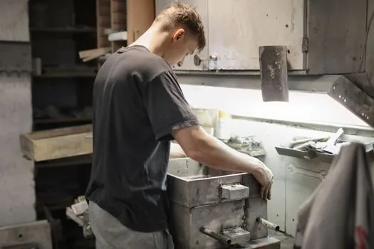
For an injection-molded magnet, the binder is not a coating: it is a structural matrix that carries the magnetic powder, sets the upper service temperature, and determines the injection-molding window. The three binders used in production are PA6 (Nylon 6), PA12 (Nylon 12), and PPS (polyphenylene sulfide), with polyolefins used in compression-bonded magnet compounds [S2][S5].
PA6 is the workhorse grade because of low melt viscosity (good powder dispersion), high toughness, and chemical resistance, with the trade-off being a higher molding shrinkage that drops sharply once the powder loading passes ~80 wt%. PA12 absorbs less moisture and gives better dimensional stability, which is why it is preferred for tight-tolerance multi-pole inner rings. PPS raises the continuous service ceiling above 200 °C and is the binder of choice when the bonded magnet must survive under-hood automotive or near-motor temperatures [S5].
Powder loading is the second key variable. A higher powder fraction raises BHmax because volumetric magnetic-phase density goes up, but it also reduces impact strength and flow length, so the engineer is trading magnetic output for mechanical robustness. Production bonded-magnet compounds sit roughly in the 80–92 wt% magnetic-powder band for NdFeB/PA6 systems, with one documented production multi-pole inner ring running PA + 90% magnetic powder as a typical upper-loading reference [S5].
Bonded versus sintered: why the magnet is in the mold at all
The reason injection-molded magnets exist as a category is geometric: a mold can produce thin walls, internal gears, and snap-fit features in a single shot, while a sintered magnet exits the press as a near-net-shape blank that must be diamond-ground to final tolerance. Sintered NdFeB reaches near-theoretical density by vacuum sintering near 1,000 °C, which is what gives it the highest BHmax of any commercial permanent-magnet family; the cost is full brittleness and a need for protective coatings against oxidation in humid service [S2].
Bonded/injection-molded magnets sit at 80–95% of the theoretical density of their powder constituent and accept polymer matrix as a non-magnetic diluent, so the absolute BHmax is lower. The trade is paid back as: complex net-shape geometry, multi-pole orientation set in-mold by an applied external field, integrated over-molding onto shafts or bushings, and inherent corrosion resistance from the binder that usually removes the need for plating [S1][S2].
Selection by application: matching material to operating envelope
For high-strength, room-temperature motor and sensor rotors, anisotropic injection-molded NdFeB is the default; the external magnetic field applied during injection sets the pole pattern directly into the part. For under-hood automotive, downhole tooling-adjacent instrumentation, or any application above ~150 °C, SmCo in PPS or high-temperature PA12 is the engineered choice. For cost-driven consumer motors, hard ferrite in PA6 is the volume benchmark. Alnico enters when the operating temperature is the primary constraint and BHmax is secondary [S1][S2][S7].
On the tool-steel side, the same selection logic applies in reverse: pick a standard mold base steel (P20, H13, S7, S50C) for any cavity that does not carry flux, and only switch to Fe-Ni, Fe-Si, or soft ferrite when the insert is itself a magnetic functional element. Mixing the two selection trees, for example by sourcing a soft-magnetic permalloy for a structural mold cavity, guarantees poor wear life and unnecessary cost, while specifying a hardened die steel for an electromagnetic pole piece guarantees flux saturation and thermal runaway. The cheapest path to a correct spec is to separate the two questions before any RFQ goes out [S6].
Process and equipment signals worth tracking
Two verifiable signals to monitor over the next procurement cycle: (1) binder-family pricing, where PA12 and PPS moves with petrochemical feedstock and directly shifts the bonded-magnet cost model, and (2) multi-pole in-mold orientation tooling, which is the process step that converts an isotropic bonded magnet compound into an anisotropic part with usable BHmax for servo and BLDC motor rotors [S1][S5]. For related die-side process decisions, mold temperature controller sizing and selection is the logical adjacent reference when specifying a bonded-magnet injection cell.