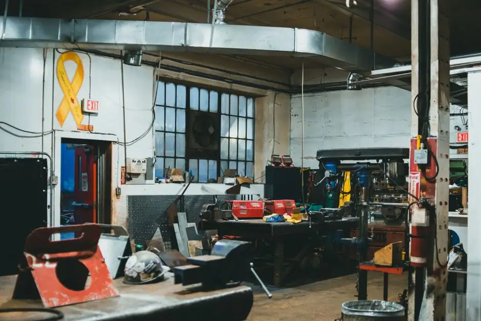
An additive manufacturing production cell groups the printer, powder recovery station, build-chamber breakout area, heat-treat furnace, support-removal bench, and CMM or CT inspection inside one footprint so a part family flows powder-to-finish in a single sequence rather than bouncing between rooms.
EPA's cellular manufacturing guidance specifies that workstations are arranged in a sequence supporting smooth material flow with minimal transport or delay, with capacity scaled by adding or removing whole cells, and with jidoka signalling at each step's end [S1]. For AM, that translation means the build envelope, depowdering cabinet, and the first metrology checkpoint sit within a few meters of each other, which is the difference between a 4-hour part-to-part handoff and a 2-day queue behind an unrelated job.
Cell Geometry and One-Piece Flow on an AM Floor
Cellular manufacturing replaces batch-and-queue with one-piece flow, where products move through the manufacturing process one-piece at a time at a rate determined by customers' needs, with right-sized flexible machines replacing high-volume dedicated equipment [S1].
The Six Sigma implementation guide states each cell handles specific product families, contains the necessary machines, tools, and skilled operators to produce these families from start to finish, and features cross-trained operators managing multiple machines, minimal distance between workstations, and built-in quality control checkpoints [S4]. On a powder-bed fusion line that translates to one operator running depowder, breakout, and bead-blast on a recurring part family, with a 5-minute walk between stations rather than a 5-minute cart ride plus queuing.
Throughput Levers: Distance, Handoffs, and the Constraint Step
Throughput improves when flow improves: a strong cell manufacturing layout brings the steps closer together, simplifies handoffs, and tightens the feedback loop when something changes, so the payoff is shorter lead times, less work-in-process, and smoother output [S3]. A batch completed at one operation but sitting before the next, then moving and sitting again at a third, multiplies across the floor; a cell reduces those delays by keeping work contained, making problems visible in minutes rather than after a cart of scrap crosses the shop [S3].
EPA's implementation method requires designing the cell around the constraint, since the slowest step sets the pace, and using autonomation so equipment signals when a cycle is complete or when problems occur [S1]. For an AM cell the practical constraints are usually the depowder + breakout bench (often 30–45 minutes per build for a 200 mm tall part in titanium) or the heat-treat furnace cycle (typically 8–12 hours including ramp and hold), not the laser exposure itself; throughput therefore scales with how many build-chambers a single depowder and furnace pair can service without queueing.
Where the AM Cell Differs from a Subtractive Cell
Multi-material additive manufacturing covers SL, laser sintering, FDM, and laminated object manufacturing, with liquid, powder, filament/paste, and solid sheet feedstocks respectively, and stereolithography in particular is noted for high fabrication accuracy [S5]. Cellular AM layouts therefore have to route powder, resin vapour, and support debris through the same U-shape that handles solid coupons, which pushes the design toward enclosed depowder stations, sealed transfer carts, and a single dust-extracted breakout booth rather than open benches.
Cellular lattice structures manufactured by AM, including Voronoi tessellations produced by stereolithography, have been validated by bending experiments up to rupture with only slight differences between CAD and printed parts, confirming that the cell concept applies both to the production floor layout and to the parts the cell makes [S2]. The two senses of "cell" share the same logic: enclose the repeating unit, control the parameters that govern its performance, and keep the boundary between units short and visible. For operations reading the spec side of AM, the additive manufacturing material reference covers the feedstock side, while construction machinery and equipment covers the powder-handling and vibration-depowder modules that sit inside an AM cell's finishing leg.
Metrics, Standards, and What to Actually Measure
Six Sigma practice measures cellular performance via cycle time per product family, first-pass yield, cell productivity, and operator utilization, with the DMAIC framework mapping cleanly to cell operations: Define the product family, Measure contained work areas, Analyze localized operations, Improve rapid implementation, and Control standardized cell operations [S4]. The lean side adds takt time, changeover time, and work-in-process value, with WIP dropping because the cell no longer buffers batches between departments [S1][S4].
AM-specific overlays include build yield (the fraction of parts that survive depowder without crack or distortion defects), first-pass dimensional conformance at the in-cell CMM, and powder-reuse cycles before virgin powder top-up, since reused powder degrades and forces a controlled refresh rate. In-process layer imaging inside the build envelope, covered in Layer Imaging Catches AM Build Failures Mid-Print, feeds the jidoka signal at the printer, while the cell-level 3D visualization vs analytics-first digital twins decision is about which layer of the cell's data stack actually drives throughput gains versus which is a visualization layer.
Who an AM Production Cell Is For, and When It Is Not
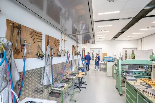
Cellular manufacturing suits job shops and high-mix operations as long as the part families share repeatable routings, similar cycle-time ranges, and similar inspection needs, and cells also shine when setup time is significant because quicker handoffs, fewer restarts, and consistent tool readiness pay off even if the machines themselves are unchanged [S3]. Mixed environments still benefit when the support steps (depowder, breakout, deburr, clean, inspect, mark, pack) are bundled into a single cell, since those steps silently clog throughput when scattered.
An AM cell is not the right answer for a single-printer prototype bureau with one job per week, where the cell overhead of dedicated depowder and inspection steals more capacity than it returns. It also fails when a part family's geometry changes every order, since the cell's whole point is a fixed routing; that case stays on a functional layout. The honest test is whether you can name a part family with stable build parameters, a recurring depowder protocol, and a recurring post-process sequence; if not, you are designing a functional department, not a cell.
Selection Criteria for the Equipment Inside the Cell
Four decision criteria sort the equipment choices for an AM cell: (1) build envelope versus part-family typical size, where the cell should match envelope to median part not maximum so the printer is not idling on small builds; (2) depowder throughput, which must clear a build in less time than the next print finishes or the cell queues; (3) heat-treat capacity, which scales with the number of printers the cell runs and is usually the binding constraint at two or more printers; (4) in-cell metrology, where a coordinate measuring machine or CT scanner inside the cell beats an external lab for cycle-time and feedback-loop reasons. [S3]
The Six Sigma guide's list of cell features (grouped equipment, cross-trained operators, minimal station distance, built-in QC checkpoints) maps directly onto those four criteria, with the cell's productivity defined as output per hour of constraint-step time rather than per printer hour [S4]. EPA adds the right-sizing rule: large, high-volume machines are replaced with small, flexible, right-sized machines to fit well in the cell, and equipment is modified to stop and signal when a cycle is complete [S1]. For lamp-cured polymer cells the lamps and light fittings and lighting equipment and electric lamps references cover the UV source selection that sets cure time inside the cell.
Trackable Signals for the Next Planning Cycle
Two signals to watch before committing capex: powder-reuse cycle counts from your existing printers (a vendor data sheet specifying refresh after N cycles versus your actual usage), and depowder + breakout cycle time measured end-to-end on three consecutive builds, not estimated. A third is the cell's takt time against the cell's constraint step, since a cell whose heat-treat furnace runs at 90% utilization is one printer away from a new bottleneck. [S1]