
Clip-on current transformers, vibration probes, and temperature sensors wired to an edge gateway can extract run, idle, and fault state from a legacy machine in under two weeks, with zero modification to the existing PLC program [S1][S5].
The approach is designed for plants whose asset mix runs from modern networked lines down to vintage presses, manually loaded cells, and semi-automatic stations that never had a programmable logic controller at all, or whose original controller is locked, discontinued, or unsupported [S1][S3][S4].
Why SCADA-style monitoring misses the long tail of brownfield assets
Extending a SCADA layer onto a mid-generation press or a 25-year-old packaging line typically requires controls-engineering hours, PLC tag additions, network firewall reviews, and historian configuration, a project path that can stall for months when IT and engineering are loaded with ERP and cybersecurity work [S1][S4].
The outcome is partial coverage: newer lines show up on dashboards with clean run/stop/alarm tags, while legacy assets are recorded only on local HMIs or paper logs, so chronic micro-stops, changeover creep, and minor faults never enter the OEE calculation [S1][S3]. Plants running 20 to 30-year-old PLCs on discontinued hardware face an even harder problem: spare parts come from pulled spares, third-party refurbishers, or surplus channels, and the supporting programming software is often tied to an obsolete OS that runs only on a kept-alive legacy laptop [S4].
Three non-invasive retrofit paths compared
Operators who need to preserve proven equipment rather than rip and replace can choose from three external-mounting paths, each with different invasiveness, sensor coverage, and data depth [S1][S2][S5]:
1. Clip-on current transformer (CT) + edge gateway: A split-core CT clamps around the motor feeder cable, the edge device classifies the current signature into running, idle, off, or per-cycle states, and OEE is computed without any cabinet work. This is the lowest-invasiveness path and works on machines that have no PLC at all [S1]. 2. Edge-native AI overlay gateway: A read-only protocol translator (EtherNet/IP, PROFINET, or Modbus TCP) sits on the OT network, listens to existing PLC tags, and adds third-party vibration or temperature sensors in parallel. The gateway streams amperage, torque, cycle time, and temperature into predictive models; the connection is strictly one-way so it cannot write back to the control loop, and deployment is engineered for under 14 days [S5]. 3. Add-on Modbus controller + sensor bundle: A small secondary controller is wired to the machine's existing controls and reads motor current, vibration, pressure, or level signals, then publishes them upstream. This works when the legacy machine has at least some Modbus exposure or unused I/O capacity [S2].
Selection hinges on four decision criteria. Invasiveness ranks CT clamps first (no cabinet entry, no PLC code change), edge overlay second (network tap, read-only), and Modbus tap-in third (panel wiring plus configuration). Sensor coverage runs the other direction: CT clamps see only the electrical signature, edge overlays add vibration and temperature with parallel sensors, and Modbus tap-ins expose the richest per-point set when the host machine already carries transducers. Integration time lines up the same way: CT retrofits install in hours, edge overlays target a 14-day window from box to insight, and Modbus tap-ins typically take days per machine [S1][S2][S5].
Sensor types actually deployed on brownfield retrofits
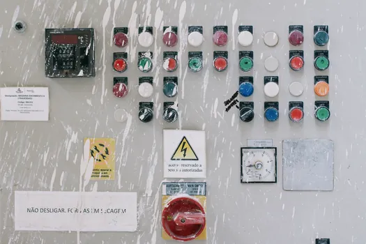
Five sensor families dominate retrofit kits: current sensors (split-core CT and Rogowski coils), vibration sensors (typically accelerometers on bearings and gearboxes), temperature sensors (RTD or thermocouple on bearings, housings, hydraulic tanks), pressure sensors for hydraulic and pneumatic circuits, and proximity or photoelectric sensors for part-counting and end-of-cycle detection [S3].
For condition-based monitoring, vibration plus temperature plus current is the most common bundle because the combination catches imbalance, misalignment, lubrication loss, and overload on rotating equipment before catastrophic failure; retrofits on this stack typically pay back through avoided unplanned downtime rather than throughput gain [S3].
What data you can, and cannot, get without touching the PLC
A CT-based readout resolves machine state into four buckets: high steady current equals running under load, low baseline current equals powered but idle, near-zero equals off, and repeating current spikes equal individual production cycles, which is enough to compute availability, performance, and a credible OEE number for most standalone cells [S1].
An edge-native overlay that taps the PLC tag list adds amperage, VFD frequency, hydraulic pressure, and cycle-time resolution to that baseline, and historian bridging via API or ODBC lets the model train on up to three years of stored data immediately on connection, which is what makes a 14-day deployment window realistic [S5].
The data that no non-invasive path can deliver without cabinet work: closed-loop setpoints, valve position feedback on proprietary buses, and any signal that the original manufacturer wired only to a local HMI with no external terminal. For those, a partial migration (a new sub-panel plus a modern PLC controller in parallel) is the next step up the ladder [S4].
Selection criteria for the right retrofit path on your floor
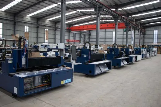
For plants whose bottleneck is invisible legacy capacity and whose engineering bench is thin, start with CT clamps on the worst-covered 10 to 20 machines; payback usually shows up in 8 to 12 weeks through identified changeover losses and micro-stops [S1][S3].
For plants already running a historian or a modern SCADA on the new lines but with brownfield gaps, an edge-native overlay is the better fit because it preserves the existing data investment and adds predictive maintenance without duplicating infrastructure; the safety PLC and control PLC remain untouched, and the read-only design carries zero risk to the running control loop [S5].
For plants where legacy assets carry hazardous-area motors or sit in classified spaces, specify sensors and edge gateways with the right hazardous-location certifications for the zone, and confirm the gateway's industrial control panel integration matches the site's lockout-tagout and arc-flash practices before mounting anything live [S2][S4].
Limits, failure modes, and what the retrofit will not fix
CT-based state detection cannot distinguish a machine that is running unloaded from a machine that is running under a commanded recipe step; it reads the motor, not the process, so cells with frequent low-load production runs will see inflated availability numbers unless a secondary sensor (cycle counter, part-present photo-eye) is added [S1].
Edge overlays depend on the existing PLC exposing a usable tag list; machines whose original control program was written in a proprietary or undocumented language, or whose only output is a panel light, force a fallback to CT or to a partial controls modernization [S4][S5].
Cybersecurity is the other constraint: any new edge gateway on the OT network must be deployed read-only and segmented from the control VLAN, otherwise the retrofit that was meant to add visibility becomes an attack surface, and IT will rightly block it [S4][S5].
Sourcing, standards, and procurement signals to watch
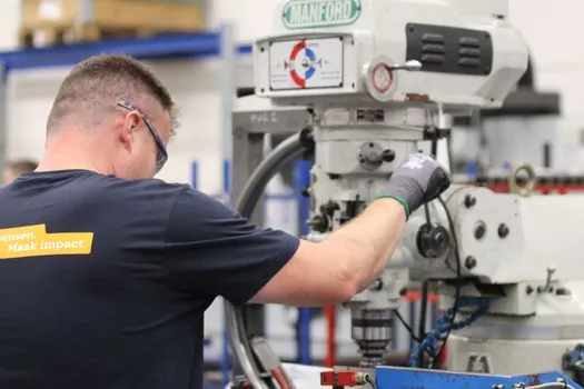
Procurement should treat the retrofit kit as three line items: the sensor bundle (CT, vibration, temperature, pressure) with stated accuracy and IP rating, the edge gateway with the protocol list spelled out (EtherNet/IP, PROFINET, Modbus TCP, OPC UA, MQTT/Sparkplug B), and the cloud or on-prem analytics layer with the data-retention contract attached [S1][S5].
Two trackable signals to watch over the next two quarters: more vendors shipping edge gateways that bridge directly into existing historians via ODBC, which removes the duplicate-data-store problem, and more pressure and flow sensors appearing in retrofit kits, since most brownfield OEE projects start with electrical state and only later add process variables like pressure transmitter and flow meter taps for energy and quality loss tracking [S3][S5].
Background reading: How to Build a Chemical Transfer Hose Spec: STAMPED Method, Tube Polymers, and Ratings.