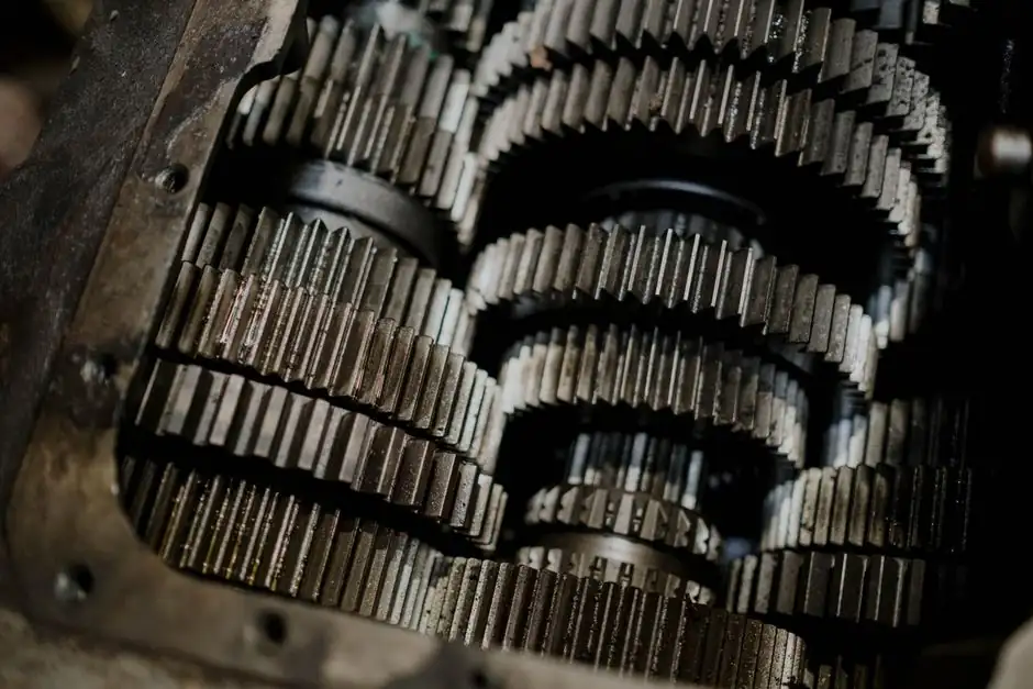
ANSI B17.1 (approved 1967, reaffirmed 1998) and ISO 773 are the two parallel-key standards that come up on every shaft-key print that crosses the Atlantic; they share the same engineering goal (a square or rectangular key sized to the shaft diameter) but use different unit systems, different fit-class conventions, and slightly different depth splits between shaft and hub [S2].
For a 25 mm shaft, ISO 773 / DIN 6885/1 specifies an 8 mm wide × 7 mm tall key with a 4.0 mm shaft keyseat depth (t1) and a 3.3 mm hub keyway depth (t2); the same physical shaft under ANSI B17.1 does not exist, because ANSI B17.1 only addresses inch shafts from 5/16 in to 13 in, with a 1 in shaft taking a 1/4 in × 1/4 in key and a 1/8 in shaft keyseat depth [S1][S3][S4].
Scope, Units, and Document Lineage
ANSI B17.1 is an American National Standard titled "Keys and Keyseats," first approved in 1967 and reaffirmed in 1989 and 1998; it covers parallel and taper keys for inch-series shafts from 5/16 in (0.3125 in) up to 13 in diameter, with square keys preferred up through 6 1/2 in and rectangular keys preferred above that line [S2]. ISO 773 is the international metric counterpart, harmonized with DIN 6885/1, covering parallel keys for shafts from 6 mm to 500 mm; the 1972 metric key standard B.S. 4235 Part 1 carries the same nominal dimensions [S5][S7].
The two standards do not overlap in nominal shaft size: a 6 mm to 500 mm shaft falls under ISO 773 / DIN 6885/1, and a 0.3125 in to 13 in shaft falls under ANSI B17.1; specifying a metric key on an inch shaft, or vice versa, is a common drafting error that puts a key with the wrong width tolerance into a hub [S4][S5].
How Each Standard Sizes a Key to the Shaft
Both standards derive key width and key height from the shaft diameter range, not from a free choice by the designer; in ANSI B17.1, a 1 in shaft sits in the 7/8 in to 1 1/4 in range, which calls for a 1/4 in wide × 1/4 in tall square key, while a 1 1/2 in shaft sits in the 1 3/8 in to 1 3/4 in range, which calls for a 3/8 in wide × 1/4 in tall rectangular key [S1][S2].
Under ISO 773, the same logic holds with metric values: a 20 mm shaft falls in the 17 to 22 mm range, calling for a 6 mm × 6 mm square key with t1 = 3.5 mm and t2 = 2.8 mm; a 50 mm shaft falls in the 44 to 50 mm range, calling for a 14 mm × 9 mm rectangular key with t1 = 5.5 mm and t2 = 3.8 mm [S4][S5]. The key sits roughly half in the shaft and half in the hub, with the hub slightly deeper than half the key height to clear any corner fillet and to provide an assembly clearance [S3].
Side-by-Size Comparison of Common Shafts
Comparing the two standards shaft by shaft gives the most direct spec map: a 1/2 in (12.7 mm) shaft is treated as an ANSI shaft and takes a 1/8 in wide × 3/32 in tall key, while the metrically nearest 12 mm shaft is treated as an ISO shaft and takes a 4 mm × 4 mm key [S1][S4]. A 2 in (50.8 mm) shaft under ANSI B17.1 takes a 1/2 in × 3/8 in key with 3/16 in shaft depth, while a 50 mm shaft under ISO 773 takes a 14 mm × 9 mm key with 5.5 mm shaft depth [S1][S5].
On a load basis, key width under both standards tracks at roughly 25% of the shaft diameter for common mid-range sizes: 8 mm key for 30 mm shaft (27%) and 1/4 in key for 1 in shaft (25%) are typical; the ratio drops slightly on the largest sizes, where a 100 mm shaft takes a 28 mm key (28%) and a 4 in shaft takes a 7/8 in key (22%) [S1][S5]. The pattern is consistent enough that a metric key can often be visually matched to an inch shaft, but the tolerances and depth splits are not equivalent and the standards must be followed individually [S3].
Fit Classes, Tolerances, and Depth Splits
ANSI B17.1 defines three fit classes: Class 1 is a clearance or metal-to-metal side fit using broad negative-tolerance bar stock, Class 2 is a tighter side fit with possible interference or clearance using close plus-tolerance key stock, and Class 3 is an interference side fit whose degree is not standardized but is often based on the Class 2 top-and-bottom fit range [S2]. A typical Class 2 keyway width tolerance on a 1 in shaft is +0.002 in / -0.000 in, with a recommended key length of about 1.5 × the shaft diameter (so 1.5 in for a 1 in shaft) [S3].
ISO 773 specifies the keyway width tolerance as Js9, which is the metric equivalent of a tight clearance fit, and pairs it with explicit t1 and t2 depth tolerances: for a 25 mm shaft the t2 hub depth is 3.3 mm nominal with a tolerance of 3.3 to 3.5 mm, while the corresponding 1 in ANSI B17.1 hub keyway depth is 0.130 in nominal versus 0.125 in shaft depth, a 0.005 in clearance to absorb corner radius and assembly stack-up [S3][S4][S5]. For broader context on how keyed joints fit into a complete shaft-to-hub assembly, see the reference page on shaft fastening methods, which positions parallel keys against setscrews, tapers, and interference fits. Shaft keyseat depth and hub keyway depth are not arbitrary; getting them right is what keeps a shaft coupling from rocking on its hub under reversing load.
Selecting the Right Standard for the Job
Use ANSI B17.1 when the shaft, hub, key stock, and keyway cutter are all inch-based; this is the default for North American process equipment, NEMA-frame motor shafts, and most general-purpose gear reducers. Use ISO 773 / DIN 6885/1 when any of the components are metric, which covers almost all European machinery, most Japanese industrial equipment, and any IEC-compliant motor shaft [S4][S5].
Do not mix standards on a single joint, even if the metric and inch keys look physically similar: a 6 mm ISO key and a 1/4 in ANSI key differ in width by 0.34 mm, but the keyway width tolerance, the depth split, and the corner radius are also non-equivalent, so a mixed joint will not carry its rated torque without rework [S3][S4]. For shafts outside the 6 mm to 500 mm or 0.3125 in to 13 in range, neither standard applies directly: very small shafts typically use setscrews or pinned connections, very large shafts move to splines or shrink fits, and a shaft collar or shaft key reference is the place to confirm the appropriate transition. For applications requiring axial sliding under load, a Class 3 loose fit in ANSI terms or a P9/D10 optional tolerance under ISO is the documented path [S2][S4].
Common Specification Errors and Verification
Three errors show up on prints that mix the two standards. First, calling out "1/4 in key" on a metric drawing, which leaves the keyway width tolerance ambiguous because ANSI Class 2 is +0.002 / -0.000 in while ISO Js9 is roughly +0.0125 / -0.0125 mm; the two have different clearances and different stock expectations [S2][S5]. Second, omitting the corner radius: ISO 773 specifies a keyway radius R that scales with shaft size (0.08 to 0.16 mm for shafts under 12 mm, up to 2.00 to 2.50 mm for shafts above 330 mm), and using a square-cornered cutter in a radiused keyseat will leave the key standing proud [S4][S5].
Third, ignoring surface finish: the ISO 773 / DIN 6885/1 specification referenced by coupling manufacturers calls for keyway sides and bottom not to exceed 250 microinches Ra, and keyseat alignment is toleranced at 0.010 in maximum offset and 0.002 in maximum lead for ANSI B17.1 [S2][S4]. When rebuilding a motor or gearbox with a replacement key, verify the actual shaft diameter with a micrometer, look up the table row for that exact range, and machine the keyseat to t1 and the hub keyway to t2 separately; do not assume the key that came out of the assembly is the right key for the reassembly [S1][S8]. A practical decision aid for selecting the right keyed joint on a motor or gearbox input is laid out in the 115 mm vs 125 mm vs 230 mm angle grinder cutting and selection map, which uses the same criterion-by-criterion format to size a tool drive end, and the 15° vs 25° vs 40° angular contact bearings spec-driven selection guide applies the same logic to bearing-side shaft fitments.
Verifying each joint against the published table row, recording the standard explicitly on the print, and ordering key stock to that standard's tolerance class remains the simplest way to keep an inch-side assembly and a metric-side assembly from being mixed at the bench.