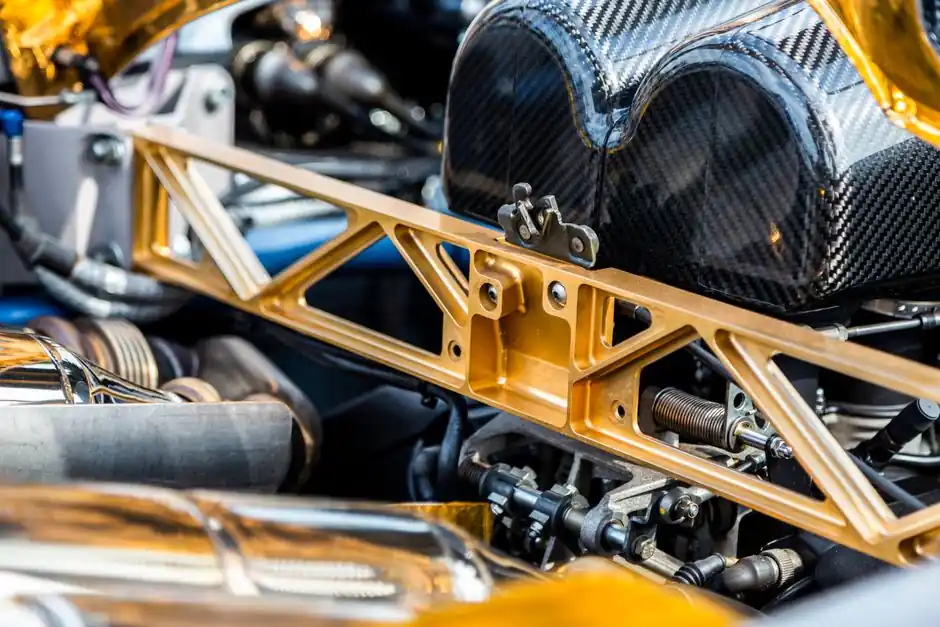
Automotive injection molding cells are typically built around IMM clamp force of 500–3,000+ tf, with take-out robot payloads of 10–50 kg including EOAT and traverse beams adjustable up to 5,000 mm [S2]. Selecting an automatic molding line for Tier 1 automotive work is a sizing problem before it is a brand problem: clamp tonnage, platen size, robot stroke, and EOAT geometry must be matched to the largest part in the program, not the average.
The same physics that drive consumer-electronics cells apply here, but the cosmetic, longevity, and traceability bars are higher. A bumper fascia or instrument-panel substrate must exit a multi-thousand-ton mold without handling marks, run for years under documented process windows, and stay inside OEM cosmetic acceptance criteria across multiple shifts [S2]. That pushes the selection toward large-format traverse robots, disciplined mold venting, and IATF 16949-grade process control rather than commodity cell hardware.
Definition and Scope of an Automotive Molding Cell
An automotive automatic molding cell combines an injection molding machine (IMM), a take-out robot, end-of-arm tooling (EOAT), and downstream stations for inspection, trimming, and packaging. The cell boundary is usually defined by the IMM platen and the robot traverse beam; everything beyond the placement fixture is downstream automation that may or may not be in scope [S2].
For automotive exterior and interior work, the IMM is almost always a large-tonnage hydraulic or hybrid press. Clamp force commonly lands in the 500–3,000+ tf range, with machines above 1,500 tf typically fitted with 3-axis Cartesian traverse robots and two-stage telescopic vertical arms to reach across the platen [S2]. The platen size, not the shot weight, often sets the upper bound on part footprint; a 1,800 mm horizontal reach and 3,000+ mm vertical stroke are typical for fascia-class tooling [S2].
Process options inside the cell follow the standard injection molding taxonomy: conventional single-shot, two-shot/multi-shot for hard-soft overmolds, insert molding for threaded bushings, and gas-assisted molding for large structural ribs [S1]. Automotive programs rarely rely on a single process variant; most Tier 1 cells are configured to switch between conventional and one of the overmold variants to consolidate parts and eliminate secondary assembly [S1].
Selection Criteria: Sizing the Cell to the Part
The first gate is clamp force, derived from projected part area, cavity count, and injection pressure. Automotive exterior trim and structural components require IMMs in the 500–3,000+ tf band, while interior trim and brackets usually land in the lower 500–1,500 tf range [S2].
The second gate is robot payload, including the EOAT mass. Large automotive parts commonly require 10–50 kg payload capacity, with the upper end reserved for fascia-class take-out where the robot must also support multi-cavity handling and downstream placement fixtures [S2]. Selecting a robot below the worst-case payload will either force cycle-rate cuts or shorten servo service life on the traverse axis.
The third gate is reach. Traverse beams on automotive cells routinely span up to 5,000 mm, with horizontal reaches of 1,800 mm and vertical strokes above 3,000 mm, sized to clear large platen dimensions and dip into deep mold cavities [S2]. A useful rule: robot reach must exceed the larger of (platen width + half-stroke) or (mold open height + part height + safety margin); if it does not, the cell will be stroke-limited and unable to use the full platen.
The fourth gate is cosmetic class. Visible parts (fascias, bezels, instrument panel top covers) cannot tolerate contact damage and force EOAT designs that distribute grip force across multiple contact points rather than concentrated suction or clamp points [S2]. This often pushes the cell toward servo-driven traverse robots with programmable contact-force control rather than pneumatic top-entry units.
Who the Cell Is For, and Who It Is Not
An automotive-class automatic molding line is built for programs running five-plus years at consistent volume, with documented control plans, first-article inspection, in-process dimensional checks, and SPC on critical-to-quality features [S3]. Tier 1 suppliers and OEM sourcing teams that need lot traceability and validated material certificates are the core customer [S3].
It is not the right fit for short-run prototyping, low-cosmotic industrial housings, or programs where total annual volume is below the break-even point for multi-cavity hard-steel tooling. Programs under roughly 50,000 parts per year rarely justify the multi-cavity, quality-steel cavity and core blocks that automotive programs depend on for cycle efficiency and dimensional stability [S3]. For those runs, a general-purpose molding line with a smaller traverse robot is usually the better economic call.
It is also a poor fit where cosmetic class is low but tonnage is high, e.g. large non-visible structural ducting. In those cases, a side-entry or beam-mounted Cartesian robot can outperform a top-entry traverse unit on cycle rate, because side-entry robots enter the mold parallel to the tie bars and offer faster take-out plus immediate stacking for high-volume production [S4].
Comparing the Main Robot Options for Automotive Cells
Standard traverse robots offer a balance of payload and reach suitable for larger items like automotive parts, with adjustable beams and telescopic vertical arms that scale with platen size [S4]. They dominate the automotive cell because they clear the mold space and place parts onto downstream fixtures in a single motion. Their weakness is cycle rate: top-entry traverse units add vertical and horizontal travel time that becomes the bottleneck on thin-wall packaging-class work [S4].
High-speed traverse robots are optimized for thin-wall packaging with very short cycle times. They sacrifice some payload and reach for acceleration, and are not the right pick for a 30–50 kg fascia take-out [S4].
Side-entry robots are built for ultra-fast cycles and immediate stacking. They are a common fit in high-volume packaging (yogurt cups, ice cream tubs), and a marginal fit in automotive where cosmetic surfaces usually force a top-entry placement that protects the visible face of the part [S4].
For automotive exterior and interior, the dominant pick is a large full-servo traverse robot with a movable kick beam, two-stage telescopic vertical arm, and multi-point EOAT sized to the part footprint [S2]. Programs that mix cosmetic exterior with structural under-hood parts often run two cells with different robot classes rather than one compromised cell.
Material, Mold, and Process Constraints
Resin selection drives both the mold steel choice and the cell's process window. Automotive programs most often run polypropylene (PP) for impact and cost, acrylonitrile butadiene styrene (ABS) for dimensional stability and surface quality, polyamide (PA, nylon) for stiffness at elevated temperature, polycarbonate (PC) for impact and clarity, plus engineered resins where mechanical or thermal load is specified [S3].
Process control has to hold temperatures, injection speed, pressures, and cooling time inside defined windows, with first-article inspections, in-process dimensional checks, and SPC on critical-to-quality features [S3]. Tooling itself usually means multi-cavity tools, quality steel cavity and core blocks, and controlled venting to support cycle efficiency and dimensional stability across years of production [S3].
Undercuts add a separate layer of constraint. External undercuts on clips, hooks, or side features are common in automotive interiors and can be solved either by shifting the parting line to split the undercut (cheap, but can leave a visible line on cosmetic parts) or by cam/slide systems that retract as the mold opens (more expensive, but built into the cycle and repeatable at high volume) [S5]. For visible interior trim, the cam/slide path usually wins because parting lines show. For non-visible clips, the parting-line path is preferred because it avoids the cycle penalty of slides and the maintenance cost of additional moving parts [S5].
Standards, Quality Systems, and Sourcing
Automotive suppliers operate under IATF 16949 quality management requirements, which extend to process consistency and traceability, including how parts are extracted and handled [S2]. On the floor, that translates to documented control plans, change management on tooling or material, and lot traceability for the life of the program [S3].
Material specifications for under-hood and exterior parts typically reference OEM-specific material standards (heat aging, chemical resistance, UV exposure, vibration) layered on top of the resin data sheet; the cell's process window must hold inside those limits across heat cycling, vibration, and chemical contact typical of road service [S3].
For organizations structuring a new automotive cell, two trackable signals are the lead time on quality-steel multi-cavity tooling (typically 16–24 weeks for a production-class automotive tool) and the availability of large-traverse servo robots in the 30–50 kg payload class, both of which gate cell start-up. Buyers evaluating a sand-cast or composite alternative for non-cosmetic structural parts may also want to review sand mixer selection for rail component foundries for adjacent foundry cell logic, since similar multi-year, high-cosmetic constraints apply to rail side panels.