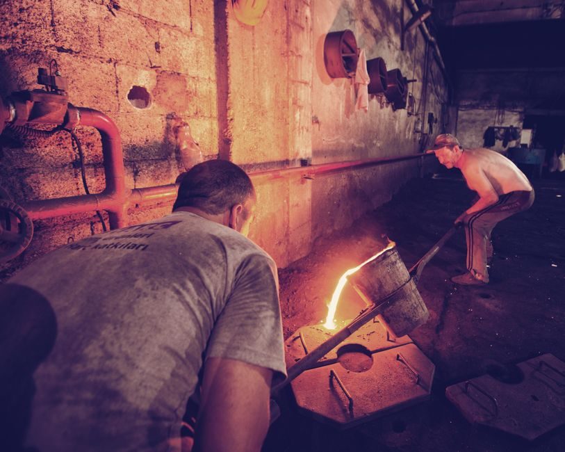
A cupola furnace installation is a multi-discipline civil, mechanical, and combustion job: refractory shell, tuyere/blower train, charge door at the top, and a pollution-control stack engineered to the same melt-rate envelope as the cupola furnace itself [S2].
Indian foundries such as P.S Trading Co. in Howrah ship cupolas alongside gear ladles, M.S. ladles, dewatering cyclones, exhaust chimneys, multi-cyclone separators, and Venturi scrubbers as one bundled scope, which is a strong tell that no single trade can install a cupola in isolation [S2].
Foundation & Civil Acceptance Criteria
Foundry-grade cupola foundations are cast as a reinforced raft or pile-supported pad sized for the live load of a charged cupola plus spill containment; the manufacturer's drawing always nominates a load case in kN/m², and that number — not the concrete grade alone — is the acceptance threshold for civil sign-off [S2].
A 1–3 t/h cupola typically sits on a 250–400 mm thick raft with a curbside spill wall forming a containment volume equal to at least 110% of the largest ladle or the cupola well-bath capacity, whichever is greater, so a lining breach drains into a capture basin instead of the shop floor [S2].
Embed plates for the cupola furnace shell, the blower skid, and the stack base must be set to ±5 mm plan tolerance and grouted with non-shrink epoxy mortar before refractory work begins; a misaligned base plate is the most common root cause of tuyere-to-tuyer asymmetry and uneven melt rate [S2].
Refractory Lining Stack-Up
Total lining thickness on a small cold-blast cupola runs 225–300 mm through the melting zone, dropping to 150–200 mm in the well and stack; the cupola furnace bosh angle is set between 15° and 25° inward to keep the charge column centred and the melt descending through the hottest zone [S2].
Anchor acceptance is simple and binary: a hammer-tap on the working lining must ring, not thud; any dull zone is cut out and re-bricked before the cure-firing schedule begins — dry-out ramps of 50 °C/h up to 600 °C, hold 4 h, then 100 °C/h to 1100 °C [S2].
Cold-Blast & Hot-Blast Train Sizing
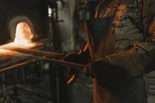
The blower package must deliver the design wind rate in Nm³/min at the tuyere static pressure (typically 15–35 kPa for a cold-blast unit, 25–50 kPa for a hot-blast recuperator-fed shell) with a 10–15% margin over the calculated stoichiometric-plus-loss figure [S2].
For a hot-blast upgrade, the recuperator sits on a separate foundation beside the cupola, tied into the shell with a refractory-lined bustle pipe; the blast temperature target is 400–600 °C, which raises thermal efficiency versus a comparable cold-blast cupola furnace by roughly 20–30 percentage points on coke rate [S2].
Tuyere count and diameter are not discretionary: most cold-blast cupolas run 4 to 8 tuyeres sized at 8–15% of the shell inner diameter, evenly spaced, each with a peep-sight, a shut-off slide valve, and a dedicated blast leg from the wind ring [S2].
Charge Deck, Stack & Spark Arrestor
The charge door is set 2.5–3.5 m above the tuyeres, with a hinged or double-leaf door and a charging skip or inclined chute; the gas take-off to the stack is taken above the charge door to maintain a natural draught of 5–10 mmWC at the charging level [S2].
Stack height is governed by local emission rules, not by the cupola builder; a 2–5 t/h unit typically needs a 18–30 m self-supporting steel stack lined with 75–100 mm of castable refractory for the first 6 m above the cupola top [S2].
Spark arrestor and dust collection sit between cupola and stack — the crucible furnace installation workflow uses the same drop-out box / cyclone / induced-draft fan arrangement and is a useful parallel reference [S2].
Pollution Control, Charging Practice & Commissioning
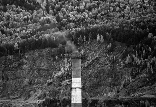
Foundry pollution kits for cupola off-gas combine a multi-cyclone, a Venturi scrubber, and an exhaust chimney with a re-circulation pump; the multi-cyclone handles 80–90% of particulates above 10 µm, the Venturi scrubs the sub-10 µm fraction down to typically below 50 mg/Nm³ at the stack [S2].
Coke-to-metal ratio for grey-iron melting is set between 1:6 and 1:8 by weight, with a flux (limestone) addition of 3–5% of the coke charge; deviation outside that band is the first diagnostic to check when melt rate or carbon pickup drifts off target [S2].
First-fire commissioning runs the cupola empty on coke and air for 2–4 h, verifies tuyere temperatures within ±20 °C of each other, then ramps to the design melt rate over the next 4–8 h; tuyere imbalance above that band is a refractory or blower-distribution fault, not an operator error [S2].
A common boundary that decides repair vs rebuild: if tuyere-zone refractory wear exceeds 40% of original thickness, patch with plastic refractory and re-rate melt capacity down; below 20% wear, continue to run. Anything in between is a judgement call that the foundry's crucible furnace TCO record will frame against downtime cost [S2].
Track two signals over the next operating quarter: tuyere-pressure trend (should stay within ±5% of the commissioning baseline) and stack opacity (should hold below Ringelmann 1 after the multi-cyclone / Venturi train is bedded in) — both are leading indicators of refractory and emissions-train health on a new cupola furnace [S2].
Spec-level background on the components involved: linear guide.