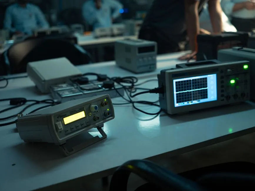
For edge detection on a vision measuring system, backlighting produces a high-contrast binary silhouette that lets threshold-based edge routines run in a single pass, while coaxial lighting is the geometry of choice when edges are engraved, printed, or otherwise defined on a flat specular surface [S5][S6].
Backlighting places the emitter behind the part, coaxial lighting routes light through a half-mirror so the illumination axis coincides with the imaging axis, and the two are rarely interchangeable because they produce opposite contrast polarities on the same feature [S1][S7].
Why backlight dominates dimensional and silhouette edge detection
Backlighting is the reference geometry for edge detection on a vision measuring machine because it creates a dark silhouette against a bright field, and that contrast polarity lets a single global threshold recover the part outline in one frame [S5][S2]. The result is a high-contrast binary image in which edge-detection algorithms run quickly and with high repeatability, which is why the geometry is described as one of the most common techniques for presence/absence and dimensional gauging in current application notes [S6].
Typical operating range of a diffuse backlight on a small field of view is 25–100 mm part-to-light distance with a collimation half-angle below roughly 5°, and edge-position repeatability on a properly telecentric station is commonly quoted in the 1–5 µm band for sub-50 mm fields [S3][S9]. Backlight is best specified when the feature of interest is the outer profile, a hole, or a slot, and the part is opaque or only mildly translucent, so the machine vision system only has to recover a single intensity transition per pixel column [S5].
Why coaxial light is required for edges on flat specular surfaces
Coaxial lighting is the geometry specified when the edge to be detected is a laser engraving, an ink mark, a scratch, or a step on a mirror-finish metal or glass surface, and the geometry works by directing light through a 50/50 beam-splitter so illumination and imaging share the same axis [S1][S7]. Because the half-mirror rejects light returning outside a narrow cone, only the surface that is perpendicular to the optical axis returns energy to the sensor, and any engraved or printed mark scatters that energy out of the cone and shows as dark on bright [S7][S4].
For sub-100 mm fields of view, working distance is typically 50–200 mm with a 25–50 mm clear aperture, and the geometry is described as ideal for flat reflective parts where directional contrast matters, in contrast to dome lighting which is preferred for curved or 3-D features [S7]. Coaxial also eliminates the shadows that plague off-axis ring lights when a feature sits inside a recess, which is why it is the default for reading characters, symbols, and 2-D codes on polished metal, silicon wafers, and display glass [S4][S8].
Decision matrix: backlight vs coaxial against four real criteria
For an engineer choosing between the two geometries for an edge-detection station, the four criteria that actually drive the decision are contrast polarity, surface finish, feature depth, and tolerance to part tilt. Backlighting wins on dimensional features where silhouette contrast is needed, coaxial wins on specular surfaces where surface features must be read without glare [S5][S7].
On a 25 mm field of view, a properly collimated backlight delivers sub-pixel edge repeatability on an opaque profile, while a coaxial light at the same working distance typically returns a 1.5–3× lower contrast ratio on the same feature but a far higher ratio on an engraving, so the two geometries are not redundant tools but complementary ones in a lighting library [S2][S6]. When the part is mirror-finish and the feature sits on the surface, backlight will simply return a saturated bright field with no readable edge, and coaxial is the only geometry of the two that recovers the feature, which is the practical rule taught in current selection guides [S4][S7][S8].
Failure modes and when neither geometry is correct
Backlighting fails on reflective or curved parts because glare and internal reflections fill in the silhouette, and it also fails on translucent parts because the light bleeds through and softens the edge by 5–20 pixels depending on material thickness [S5][S2]. Coaxial lighting fails on parts with significant height variation, because only the surface at the focal plane returns signal, so features 0.5 mm above or below the focal plane drop below the contrast threshold of typical edge routines [S7].
When neither geometry fits, the standard fallback in current application notes is a dome or diffuse bright-field light for curved 3-D parts, and a dark-field ring for scratch and defect detection on specular surfaces, with both alternatives specifically named as the geometry of choice when backlight or coaxial cannot deliver the required contrast [S3][S4]. A 1 mm tall embossed character on a brushed aluminum faceplate is the canonical case where coaxial is the wrong tool: a low-angle dark-field ring will resolve the embossed edge while a coaxial will return a near-uniform field [S4].
Integration notes for a vision measuring system station
Backlight units on a modern vision controller are typically driven with a constant-current LED driver at 24 V DC with 0–10 V analog or PWM strobe, and strobing at 1–10 kHz is common to freeze motion on indexing conveyors while keeping average LED current within the 350–700 mA band typical of high-output machine-vision LED panels [S2][S10].
Mechanical layout for a backlight is straightforward: emitter behind the part, camera on the optical axis, no beam-splitter in the path, and total stack height from emitter to sensor typically 100–250 mm on a 25–100 mm field of view. Coaxial layout adds the beam-splitter cube or plate, which lengthens the optical path and forces a minimum 50 mm working distance, and the cube or plate must be sized at least 1.2× the camera aperture to avoid vignetting the corners of the field [S3][S7].
Selection rule of thumb for a new edge-detection station
If the feature is the outer profile, a hole, or a slot on an opaque part, specify a collimated backlight on a telecentric lens and run a single-threshold edge routine; if the feature is an engraving, print, or surface step on a flat specular part, specify a coaxial light with a 50/50 cube and run a localised threshold or blob routine on the dark-on-bright image [S5][S6][S7]. For a 25 mm field, a 1.5 µm/pixel camera, and a target edge repeatability of 5 µm or better, the backlight path is the shorter integration, the coaxial path is the only viable one for surface-mark edges, and a station that must inspect both feature classes carries both lights with software-selected switching rather than a single compromise geometry [S2][S9].
Track the contrast ratio on a calibration target during commissioning: a backlight station on an opaque profile should return 200:1 or better, and a coaxial station on a laser mark on polished steel should return 50:1 or better; if the measured ratio is below those bands at the planned exposure, change the geometry before changing the camera, because lighting equipment and electric lamps selection is consistently described as the highest-leverage decision in vision-system design [S2][S10].
For related coverage, see Generic Resistor vs VFD Brake Resistor: When Substitution Works.