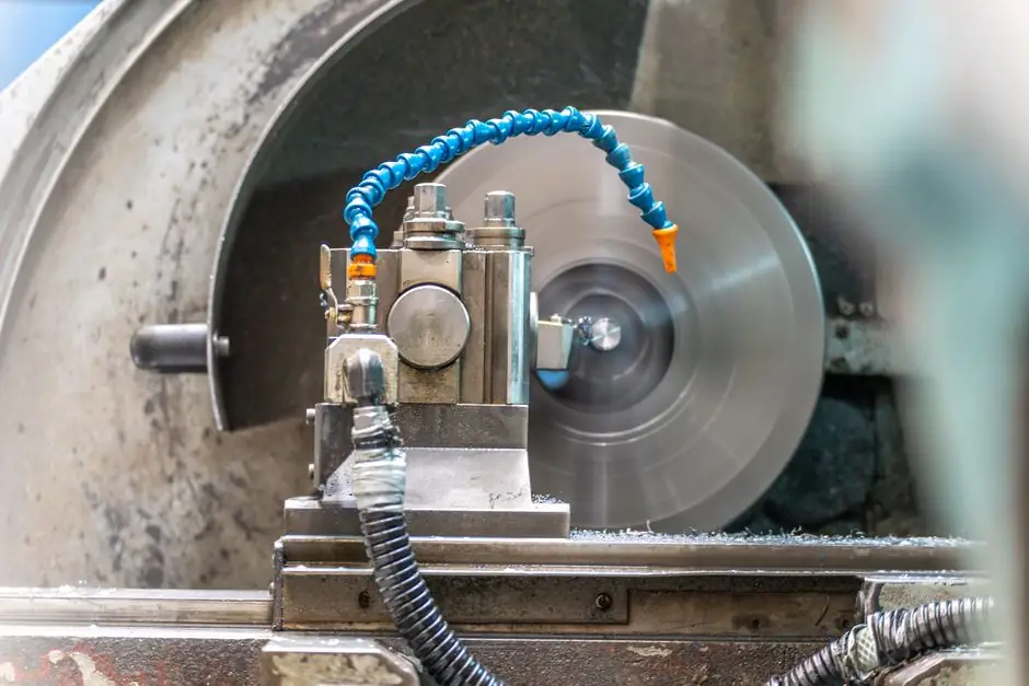
Turbocharger core balancing at operating speed is a separate quality gate after component balancing, with an oil-fed assembled rotor evaluated for vibration across its operating range [S1][S2].
A passenger-car turbo core runs well beyond 100,000 rpm, and because permissible unbalance scales inversely with speed, the residual allowed on a part that small and that fast is very small indeed.
Why Low-Speed Component Balance Is Not Enough
Component balance addresses mass eccentricity before assembly, but it cannot predict how a complete core behaves on its hydrodynamic oil film. The rotor rides on a floating oil film, and its behavior at speed is not what a low-speed measurement predicts.
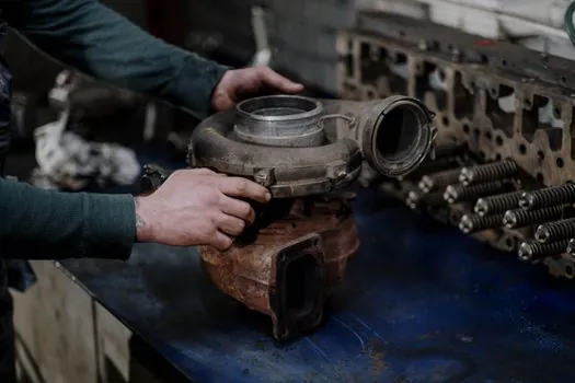
A suitable workflow starts with individual low-speed balancing of the turbine wheel and shaft and compressor wheel, followed by high-speed balance of the assembled core on an oil feed [S1][S2].
The distinction matters most on small, high-speed units because their low rotating mass and high rotational speed amplify residual stack-up unbalance. Documented symptoms include oil leakage from the bearing-housing ends and high-pitched “screaming” caused by rotating-assembly vibration [S4]. For a broader comparison of balancing approaches, see Shop vs In-Situ Balancing: Selection Guide.
Operating-Speed Rig Requirements
An operating-speed core rig must reproduce service conditions closely enough to expose bearing-clearance, oil-film, stack-up and shaft-dynamic effects rather than merely amplify a low-speed reading [S1]. The core runs on an oil feed while the machine evaluates its vibration signature at or near service speed and across the relevant operating range [S1][S2].
Oil supply pressure and temperature are process variables that need control, not incidental plumbing settings, because the shaft center position changes with speed and oil conditions [S1].
The rig also needs safe acceleration through critical speeds. The dynamic balancing machine category covers machines designed to evaluate rotor behavior dynamically rather than infer it from static displacement.
Component and Assembly Options Compared
Low-speed component balance, low-speed rotating-group balance and high-speed core balance solve different problems. The correct choice depends on production volume, repair scope, available correction access and whether the acceptance criterion must represent installed behavior. [S1]
This method is not suitable for every rotor type. Balance Technology Inc. builds balancing and measurement equipment for the rotors and housings of positive-displacement superchargers.
Correction Limits and Reject Logic
Correction must remain inside the component’s allowable material-removal envelope.
This is essential because the nose, hub face, shaft shoulders and wheel back face are not arbitrary correction locations: excessive removal can alter mass, geometry, strength or the intended aerodynamic profile.
Unbalance is expressed as mass multiplied by radius, and historical turbocharger practice uses units such as gram-inches and milligram-inches [S4].
What the High-Speed Measurement Reveals
High-speed core balance evaluates the assembled rotor where low-speed balancing cannot: the response depends on floating-bearing clearance, hydrodynamic oil-film behavior, component stack-up and load-dependent shaft dynamics [S1]. For a core machine, this makes vibration acceptance a functional test of the assembled rotating system, not merely a quality check on two wheels.
Acceleration and balance settings also depend on the distinction between VSR high-speed balancing and conventional low-speed CHRA balancing.
Who Needs This Process
High-speed core balancing is appropriate for remanufacturing operations that require repeatable installed-state acceptance, production lines with defined vibration limits and workshops handling small high-speed CHRAs where stack-up can cause leakage or noise [S1][S4]. It is also useful where component-level data cannot demonstrate that the assembled core will remain acceptable through its operating range [S2].
It is not automatically required for every repair operation. A custom rebuild can sometimes meet the intended result through critical component inspection and careful assembly, although higher-volume builders benefit from CHRA balancing because it supplies process control and knowledge of the completed assembly [S4]. Even then, high-speed balance does not replace inspection of bearings, oil passages, fasteners, wheels and the shaft, nor does it verify every condition that affects turbocharger life.
A practical acceptance record should identify the core configuration, component balance results, oil pressure, oil temperature, speed range, measured vibration and the correction decision. That record links the final result to the shell-core machine or assembly process that created the stack-up being evaluated.
Implementing a Repeatable Quality Gate
A repeatable quality gate begins with low-speed component balance and ends with an oil-fed, operating-speed core test across the specified speed range, with correction limits enforced by machine control [S1][S2]. The rig must control oil pressure and temperature because otherwise measured vibration cannot be compared reliably between cores or between production shifts [S1].
Track 3 signals for each production lot: residual vibration at the specified acceptance speed, maximum vibration across the operating range, and the correction mass or material removed at each approved plane. Any increase in correction demand can identify drift in component balance, assembly stack-up or bearing fit before it becomes a field failure.
For the broader rotor-balance workflow, distinguish a cold-box core machine from a hot-box core machine by the actual assembly and test scope, then verify that the selected rig supports the core geometry, correction planes, speed range and oil-feed conditions. Do not infer operating-speed qualification from a machine that performs only low-speed component balance.