
Ball spline shafts can be supplied with single- or two-step diameter reductions, ring grooves, coaxial holes, external threads, and smaller end or center diameters [S1].
The decision boundary is the shaft geometry: standard ball spline diameters span 4–100 mm, while groove profile, hardness, accuracy class, and end-feature depth determine what can be machined without damaging the working surface [S2].
Ball Spline End-Machining Options
A catalogued ball spline end can include a single-step reduction, a two-step reduction, a ring groove, a coaxial hole, or an external thread [S1]. These features cover common interfaces between the spline shaft and bearings, couplings, actuators, fixtures, or neighboring machine members.
NB specifies shaft-end machining, spline-nut machining, and surface treatment as custom operations, confirming that the shaft ends and nut are separately configurable [S2]. Its published shaft range begins at 4 mm and extends to 100 mm, with cylindrical nut types SSP and SSPM and flanged types SSPF and SSPT [S2].
The engineering distinction is whether an end feature merely transitions the shaft to a smaller journal or removes material that intersects the ball-contact geometry. A coaxial hole and an external thread can be added around an un grooved journal, whereas a reduction must preserve the shaft diameter and groove profile through the transition.
For assemblies that also need a keyed mounting interface, the ball spline should be treated as a rotating torque-transmitting shaft, not as a linear rail with an incidental round end.
Groove Geometry Sets the Machining Envelope
Ball splines use rolling ball elements retained in a circulating design to provide low friction, effective torque transfer, and smooth linear motion [S3]. The same geometry distinction influences load capacity, precision, speed, smoothness, and contact angle [S3].
Thomson states that its precision ball splines use linear grooves to guide balls along the shaft, providing low-friction motion and transmitting torsional loads [S1].
Such a non-circular functional section leaves less freedom for arbitrary end geometry than a plain round shaft, so any reduction or thread must terminate outside the active raceway zone.
A criteria-based comparison is straightforward: Gothic-arch grooves favor rigidity, moment capacity, and positional accuracy; circular-arc grooves favor smoother motion, lower resistance, quieter operation, and lower friction; a plain un grooved shaft journal is mechanically simpler but provides no ball-spline torque path [S3]. End machining should therefore be selected against the groove type rather than shaft diameter alone.
Hardened Grooves and Achievable End Geometry
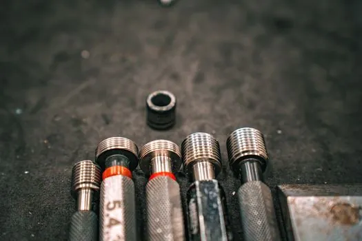
Hardened spline shafts cannot be treated as freely machinable mild steel, because the working surface must preserve groove form, contact angle, surface finish, and dimensional accuracy after heat treatment or material selection. [S2]
Engineering literature identifies high-strength alloy and hardened-steel constructions with surface treatments for wear resistance, but it does not establish a universal hardness limit, minimum remaining web, or universal grindability limit [S3].
Consequently, no defensible figure can be assigned to a generic hardened shaft without its material condition, heat-treatment specification, diameter, groove profile, and machining sequence. The drawing must identify whether ends are turned before hardening, ground after hardening, or supplied as finished ground surfaces.
A hardened finished shaft may offer wear resistance while narrowing the feasible cutting depth, but the actual cut allowance still depends on the approved manufacturing route.
For operators, the ball bearing interface should be separated from the spline raceway. A bearing journal only needs to satisfy the bearing seat and retention requirements, while the spline shaft must retain its raceway geometry, so combining both jobs into one uncontrolled diameter reduction is poor practice.
Selection Rules for Reductions, Threads, and Holes
A single-step reduction is appropriate when the mating component needs one smaller cylindrical seat. A two-step reduction provides two distinct diameters, which is useful when a separate shoulder or interface must be controlled between features [S1].
Coaxial holes should be specified by axis, diameter, depth, and whether they are through or blind features. External threads require an explicit thread form, nominal size, pitch, length, class, and treatment of the transition into the shaft body. None of these dimensions can be selected safely from the spline diameter alone.
Ring grooves serve a distinct purpose from shaft reductions because they retain a component axially without creating a smaller load-carrying journal [S1]. Their geometry should include diameter, width, position, and edge treatment. The ring groove must also avoid the ball path and bearing seat, or its retention function may conflict with the operating load path.
For rotary gripper or actuator assemblies, the arrangement should be checked against the ball spline selection for a rotating robot gripper axis. That application is suitable when simultaneous linear travel and torque transfer are required, but end hardware still needs a defined axial and rotational load path.
Accuracy, Preload, and End-Feature Interactions

NB states that preload can increase rigidity and positioning accuracy while preserving torque transmission through the effective ball and groove contact angle [S2]. End machining must not distort the spline nut seat, raceway alignment, or preload response.
Ball spline shaft configurations can contain two to six grooves, but six grooves can occupy enough of the shaft circumference that the nut must protrude for ball recirculation. The common four-groove arrangement permits side-by-side active and recirculating paths in a more compact package [S5].
These configurations establish different transition requirements. A four-groove shaft must preserve four uninterrupted working lands and adequate surrounding material for the nut, while a six-groove shaft leaves less un grooved circumference available for a reduction, thread, or ring groove [S5].
Accuracy selection should not be inferred from end finish alone. A machined journal can be concentric with the shaft while the working grooves remain inaccurate, or a high-accuracy groove can be undermined by an eccentric coupling interface. The ball spline accuracy grades should therefore be evaluated separately from the end-machining specification.
Failure Modes and Machining Review
The first failure mode is cutting into a working raceway. Grooves form the rolling and torque-transfer surface, and their geometry determines contact angle, rigidity, and load capacity [S1][S3]. A reduction or ring groove that encroaches on that surface can reduce contact consistency and invalidate the intended performance class.
The second failure mode is confusing shaft diameter with shaft stiffness. Ball spline capacity depends on ball contact area, groove shape, nut and raceway length, tolerances, shaft rigidity, and mounting method [S5]. Reducing only the end diameter does not reduce the working-section rating, but it can lower bearing load capacity or increase stress concentration if the transition is underspecified.
The third failure mode is ordering a hardened part before defining the manufacturing route. Heat treatment, final grinding, and end machining interact through remaining stock, datum selection, distortion, and grind allowance. A drawing that names only “hardened” and a final diameter leaves the process engineer to infer the critical machining limits.
A usable release should include the spline diameter, groove count and profile, accuracy requirement, nut type, shaft material, hardness requirement, surface treatment, end-feature dimensions, datum scheme, and edge-condition requirements. Available spline nut choices include SSP, SSPM, SSPF, and SSPT, while SUS440C or equivalent stainless construction is also available [S2].
The next verification step is a 1:1 drawing review comparing every end feature against the active groove zone, bearing seat, nut travel, and mating hardware. The second trackable signal is the supplier’s manufacturing sequence, particularly whether the final groove and end surfaces are ground, hardened, or finished before final inspection.