
What the 13 µm per 100 mm tolerance controls
Groove twist is the longitudinal distortion of the machined spline tracks, and it is distinct from spline-nut radial runout, flange perpendicularity and shaft-end perpendicularity [S3][S4].
This is a geometry requirement on the shaft, not a generic angular-backlash specification. Angular backlash depends on preload and clearance, while the groove-twist limit governs straightness and twist of the load-bearing tracks along the shaft [S1][S2].
How the tolerance scales with spline length
The same distinction between angular twist and linear groove distortion matters when comparing suppliers. A catalogue may instead publish a torsion-angle limit, so engineers should confirm whether the specification is expressed as displacement over 100 mm, angle over 1000 mm, or another acceptance datum [S2].
Accuracy grade versus angular-backlash specification
NB separates shaft accuracy, spline-nut accuracy and rotational-direction preload or clearance into different catalogue controls [S1][S4]. A groove-twist limit must not be used as a substitute for an angular-backlash requirement.
MISUMI states that ball splines can provide highly accurate linear motion when preload is applied, can transmit torque, and can guide radial loads and rotational torque simultaneously.
Preload also changes rotational behavior. Applying preload supports highly accurate linear motion, while groove design and preload determine rotational rigidity and resistance to angular clearance [S1][S3]. For a detailed architecture comparison, see When to Choose a Ball Spline Over a Keyed Shaft.
Converting groove twist into an angular criterion
A linear groove-distortion limit and a torsion-angle limit are different acceptance measures. The 13 µm/100 mm specification is a displacement criterion, whereas
Do not directly declare the 13 µm/100 mm and 0.25° per 1000 mm limits equivalent. Their test definitions, effective-length treatment and measurement directions must be confirmed before conversion, and the ball spline drawings should define the datum for the actual inspection.
Where the 100 mm criterion applies
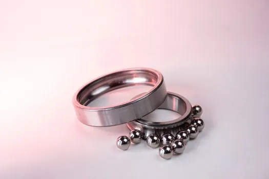
Ball splines combine linear travel and torque transmission in one shaft. Their raceway grooves carry radial and torsional loads, while the nut body supports the assembly; the resulting shaft twist remains part of positioning and transmission accuracy [S1][S3].
That operating margin should be separated from the 13 µm/100 mm manufacturing tolerance [S4].
What to put on a procurement specification
Add the shaft diameter, spline length, travel stroke, accuracy class and groove orientation, because available standard shaft diameters span 4–100 mm and those variables affect the product variant and inspection conditions [S1][S6].
Also identify the acceptance method: a selected 100 mm segment, proportional scaling, or the supplier’s torsion-angle test with a stated gauge radius and length. Require the inspection report to identify the measured length and conversion basis, rather than accepting an unqualified “precision grade” label [S2][S3].
The traceable signal is a supplier drawing or inspection record that states 13 µm/100 mm, the measured effective length and the exact groove examined. A second useful signal is confirmation that the limit remains distinct from rotational clearance, radial runout and flange perpendicularity [S3][S4].