
A rotary ball spline for a pick-and-place spindle must handle simultaneous linear travel and rotary motion while transmitting torque without angular backlash; selection begins with stroke, velocity, applied load, mounting space, duty cycle, required life, and accuracy [S3][S4].
Ball-spline selection includes high-torque, medium-torque, and rotary types, while a rotary ball spline provides simultaneous linear and rotary motion.
Define the rotary spindle duty before choosing a type
Three functional families are available: high-torque, medium-torque, and rotary ball splines, with the selection tied to the intended use [S2][S8]. A rotary spline is appropriate when the driven member must translate and rotate at the same time, whereas a conventional spline is primarily used for straight linear motion with torque transmission [S2][S4].
For a pick-and-place mechanism, the required operating envelope must be recorded before a diameter is chosen. The minimum dataset includes stroke length, velocity, applied load, mounting space, duty cycle, required life, dimensions, installation direction, environment, and accuracy [S3][S4]. A spindle that reverses direction frequently should not be selected from peak torque alone, because repeated acceleration, deceleration, and reversing cycles determine the fatigue and thermal demand.
Use the ball spline format as the mechanical reference, but keep the spindle arrangement in view. In one documented pick-and-place arrangement, the spline is supported by a ball bearing at both ends and rotation is transmitted through a pulley, with position sensors added where required [S7]. That arrangement separates the spline's linear guidance duty from pulley-driven rotation and must be included in the load and installation calculation.
Choose angular-contact or crossed-roller support
Rotary spline nuts are supported by either angular-contact ball bearings or crossed-roller bearings, and these options have different performance envelopes rather than serving as interchangeable assumptions [S4]. A rotary spline nut may ride on angular-contact ball bearings or crossed roller bearings, and the choice depends on the application's requirements.
The nut construction affects integration. When the shaft is fixed, a standard spline can use turned-down ends for radial bearings; when the nut must be fixed, the radial bearing is mounted around the nut and the assembly becomes bulkier. For the shaft arrangement used in the cited pick-and-place design, the ball bearing supports at both ends should be checked as part of the total spindle stiffness and moment load [S7].
Compare load, speed, and packaging criteria
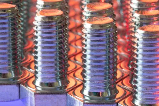
The SLS/SLF caged-ball group has nominal shaft diameters from 25 to 60 mm. These ranges show that shaft diameter alone does not identify a pick-and-place spindle solution: torque class, support construction, and required stroke determine the family.
Caged-ball models SLS and SLF use 25 to 60 mm nominal shafts. Their controlled ball circulation is intended to reduce ball collision and mutual friction, lower noise and particle generation, retain grease, and support stable high-speed response [S2]. These characteristics favor cycles involving rapid reciprocation, but the vendor catalog still requires comparison against actual velocity, acceleration, duty cycle, load, and required life [S2][S3].
Apply preload without treating torque as the only requirement
The selection is therefore a trade between rotational command accuracy, drive torque, heat generation, wear, and service interval, not a simple rule that more preload is always better.
For a servo-driven pick-and-place spindle, calculate the torque needed to accelerate the moving assembly and tooling, the reaction torque from the part or process, and any holding requirement at rest. Then check whether the selected spline's rated torque and calculated life include those combined effects. The drive must also absorb the friction created by the chosen preload; otherwise servo sizing, positioning repeatability, and thermal performance can all be compromised.
Accuracy should be specified as a measurable output. The cited rotary-spline application describes simultaneous linear and rotary motion with sub-millimeter accuracy, positioning the mechanism within fine-pick-and-place work, but that figure is not a universal spline rating [S4]. The drawing tolerance, encoder resolution, bearing preload, shaft alignment, and load deflection must all be included before assigning an accuracy target to the assembled spindle.
Match the spline to the pick-and-place architecture
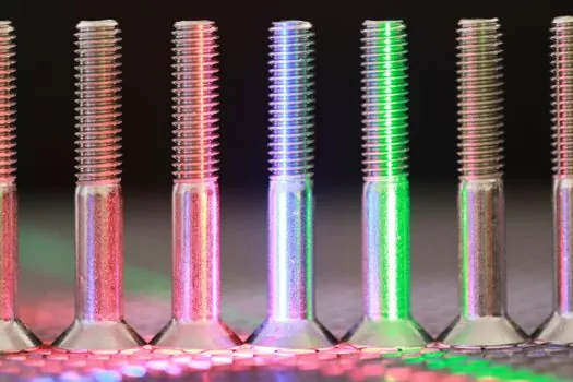
Rotary ball splines are used where twisting and linear travel occur together, including high-speed pick-and-place applications [S6]. The ball bearing arrangement remains part of the mechanical system because it supports the rotating shaft and controls radial deflection, while the spline provides linear guidance and torque transfer.
Three layouts deserve comparison. A rotary spline gives the most integrated package when the tool must travel and rotate continuously, but it adds bearing selection constraints inside the nut [S4]. A standard spline plus two end-supported ball bearings offers a simple shaft layout and can transmit rotation through a pulley, matching the cited pick-and-place mechanism, but the supports and shaft shoulders must be sized separately [S7]. A medium-torque spline is appropriate when the duty is mainly linear motion, intermittent rotary positioning, or a whirl-stop function rather than sustained combined motion [S2].
A crossed-roller guide can also serve applications requiring linear guidance and rotational support, but it belongs to a different selection path from a torque-transmitting ball spline. It should not be substituted simply because its envelope appears favorable. Confirm whether the application requires torque through the nut, continuous relative rotation, or only linear travel.
Check constraints, maintenance, and supplier data
The mechanical envelope must include the ball-spline nut, end supports, pulley, belt, encoder or position sensors, cable routing, lubrication access, and guarding. The rotary bearing-supported nut can reduce assembly bulk, but installation direction, dimensions, and environmental exposure still constrain the final package [S4]. Position sensors may be required by the control architecture, as shown in the two-end-supported pick-and-place design [S7].
Lubrication is not an afterthought. Caged-ball SLS and SLF models are designed to retain grease and support maintenance-free operation, while conventional designs require the supplier's lubrication interval and lubricant specification to be followed [S2]. The selection record should therefore identify the lubricant, relubrication interval, seal arrangement, allowable speed, rated load, and calculated life for the actual duty cycle.
Do not assign a generic load or speed rating without a matching manufacturer model. THK lists several different shaft diameters within each family, including 4 to 100 mm for LT, 15 to 150 mm for LBS/LBST, and 25 to 60 mm for SLS/SLF [S2]. Obtain the dimensional drawing, accuracy table, rated torque, allowable speed, load, life, preload, mounting, and lubrication data for the exact model before releasing the spindle design.
Shortlist by motion and support requirements
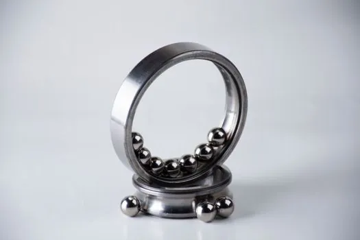
Select a rotary ball spline when the pick-and-place spindle must combine linear travel with continuous rotation and limited angular backlash. Select the caged-ball SLS or SLF architecture when rapid response, low noise, low particle generation, and retained lubrication are priorities, then verify the exact model against speed and life [S2]. Select a high-torque LBS/LBST architecture when reaction torque and moment rigidity dominate, using its 120° three-crest layout, six ball rows, and 45° contact angle as design references [S2].
For a separately supported shaft driven by a pulley, compare the standard spline with two ball-bearing supports against the integrated rotary nut. The separate-support architecture is mechanically straightforward and appears in a documented pick-and-place arrangement, but the rotary spline can reduce package bulk by integrating radial support [S4][S7]. The final shortlist should contain the selected spline family, exact nominal diameter, stroke, support method, preload grade, required life, lubrication method, accuracy target, and verified speed and load limits.