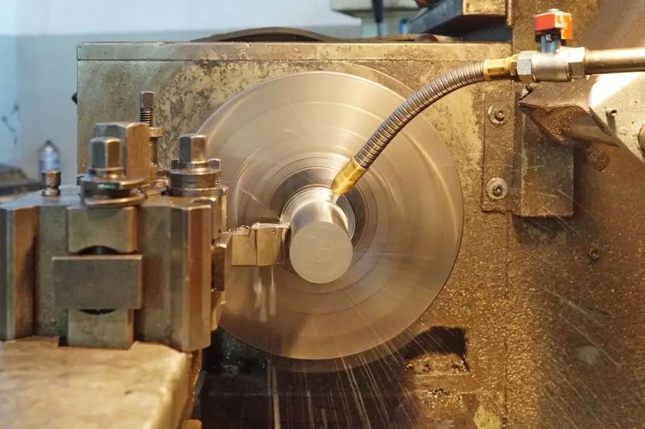
A ball screw spline combines a drive element and a guidance element on one shaft, supporting linear, rotary, and spiral motion in a compact arrangement [S1].
A conventional ball screw converts rotary input into axial travel, while a ball spline provides low-friction guidance and torque transmission [S3].
Define the motion architecture
A ball spline is a rolling-element guidance system with axial grooves machined into a round shaft; the spline nut constrains rotation while transmitting torque and supporting radial loads [S3][S4].
A ball screw uses recirculating balls in a nut to convert screw rotation into linear displacement. In a common fixed-screw arrangement, the nut travels while remaining anti-rotation constrained; a driven-nut arrangement rotates the nut while the screw remains stationary [S1].
A ball screw spline integrates both functions. A ball screw spline combines a ball screw, which serves as the driving element, with a rotary ball spline, which serves as the guiding element. THK likewise identifies rotational, linear, and spiral modes on one shaft [S7].
A ball screw spline combines the drive function of a ball screw with the guiding function of a rotary ball spline.
Compare the principal options
On motion modes, a conventional ball screw provides rotary-to-linear conversion, a ball spline provides guided linear travel with torque capability, and a rotary ball spline provides rotation plus translation without screw-generated axial drive [S1][S3].
A ball screw spline can provide linear, rotary, and spiral motion in a highly rigid, compact design. Separate ball screw and ball spline axes are easier to commission and isolate when the two motions must be positioned independently.
On packaging, combining the functions on one shaft reduces the number of parallel guide and drive packages, which is valuable in SCARA robots, assembly machines, tool changers, and pick-and-place equipment [S2][S3][S5].
On mechanical simplicity, a standalone ball screw plus a ball spline requires more shafts, supports, couplings, and controls, but separates guidance failure points from drive conversion. A ball screw spline increases integration complexity because coupling, motor sizing, bearing arrangement, and stroke become one coupled design problem [S1].
The direct decision is straightforward: specify a ball screw spline when the mechanism benefits from one shared shaft and coordinated multi-mode motion. Specify separate components when independent tuning, simpler diagnostics, or standard drive sizing outweigh package size.
Choose the appropriate machine role
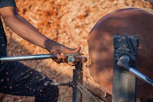
Ball screws fit positioning axes where a motor must convert rotation into controlled axial travel, including fastening, clamping, and feed applications. Their operating requirement is defined by screw lead, screw diameter, nut arrangement, support bearings, lubrication, and service life rather than by a requirement to expose shaft rotation. [S2]
Ball splines fit robots and transport mechanisms that must combine radial loading with torque transmission. Their spline shaft can be machined because it retains a round-shaft form, and NB specifies shaft diameters from 4 mm to 100 mm, with stainless steel options including SUS440C or equivalent [S4].
Rotary ball splines suit SCARA robots, assembly equipment, tool changers, loaders, and pick-and-place machines where linear and rotary movement must occupy one axis [S3][S5]. A rotary ball spline is guidance-focused, while a ball screw spline adds screw conversion to the same shaft [S1][S5].
Do not use a ball spline as a substitute for a positioning screw when the duty cycle depends on high axial positioning accuracy, defined screw lead, and repeatable clamping force. Do not use a conventional ball screw when the payload must rotate and translate together without a second guide system.
Control linear, rotary, and spiral motion
In a conventional ball-screw arrangement, the screw is driven while the nut is prevented from rotating, causing the nut to travel along the screw shaft.
In another ball-screw design, the nut is driven while the screw remains stationary, causing the nut to traverse the screw as it rotates.
This is the basis for combining movement modes without switching between separate axes.
NB documents separate SPBR and SPBF motion patterns for ball screw splines, while its product family supports positioning, linear motion, rotary motion, and combined spiral motion [S4][S5]. For control design, model the two drives as coupled actuators, not as one motor with an arbitrary rotation command.
Account for load, accuracy, and installation constraints
Spline geometry, preload, and clearance govern torque transmission, rigidity, and positioning accuracy. Increasing preload improves rotational rigidity and positioning accuracy, so zero-clearance selection is not automatically the best operating condition [S4].
NB also provides accuracy classifications for rotary ball splines and dedicated sections for ball screw spline accuracy, preload, nut orientation, operating conditions, and lubrication [S4]. Supplier-specific accuracy tables must be checked against the required shaft rotation and axial positioning rather than inferred from nut size.
Rotary support can use angular-contact bearings, crossed rollers, or gears. Each arrangement changes radial and moment-load capability, torque behavior, envelope, and assembly requirements [S1]. A preloaded angular-contact arrangement may suit applications requiring higher rotational rigidity, while crossed rollers provide a compact torque path; the final choice must follow the manufacturer load table and mounting drawing.
Environmental limits also matter. Selection factors include speed, load capacity, and operating environment [S3]. Seals and lubrication must be specified for dust, chips, coolant, or washdown exposure. For stricter contamination-control decisions, compare the ball spline seal design for dust and contamination protection with the selected shaft material and operating environment.
Apply the selection method
First define the required motion matrix: linear only, rotary only, continuous spiral motion, or independently commanded rotation and translation. A conventional ball screw satisfies rotary-to-linear positioning, while a ball spline or rotary ball spline satisfies guided translation with rotation or torque transmission [S1][S3].
Next calculate the required axial load, radial load, overturning moment, torque, speed, and positioning accuracy. For a ball screw spline, include both the ball-screw nut and spline nut in the load path, then verify shaft strength, allowable rotational speed, rated life, and deflection using the manufacturer calculation method [S4].
Then compare two architectures. A combined ball screw spline is the stronger choice for compact robotic axes, coordinated rotation and translation, and shared shaft integration. Separate ball screw and ball spline axes are the stronger choice when the two functions require independent feedback, independent fault isolation, or simple commissioning.
Finally verify mounting, lubrication, seals, stroke, nut orientation, and end-support arrangement against the selected model. The published NB catalog covers standard and maximum lengths, dimension tables, operating conditions, lubrication, and mounting for ball spline, rotary ball spline, and ball screw spline families [S4].
A trackable decision record should list the five commanded motion combinations, the required axial speed and rotational speed, the three load components, target accuracy, contamination exposure, and whether motor or nut failure must isolate one axis.