A ball spline uses one grooved shaft to guide axial travel and prevent nut rotation, whereas a conventional round-shaft linear bushing requires a second guide or restraint when rotation must be limited [S1][S3].
The decision depends on required torque, radial and axial load, carriage moments, stroke, duty cycle, mounting space, and whether the second rod functions only as an anti-rotation stop or also provides structural support [S2][S4].
Architecture Difference: One Shaft Versus Two
A conventional linear bushing rides on a cylindrical shaft and does not provide a positive torque connection between shaft and bushing. If the carriage must not turn, a second shaft or key is required, with the two spaced shafts also helping resist a carriage moment through a force couple [S1][S2].
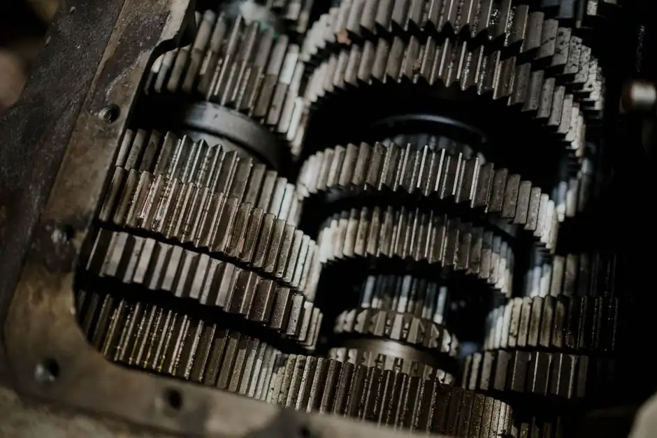
A ball spline has longitudinal grooves in the shaft and matching raceways in the nut. Recirculating balls travel in those grooves, allowing axial sliding while constraining the nut against rotation and providing a path for torque transmission [S2][S3]. The shaft is the structural member in either case, but the interface and allowable load path are not interchangeable.
The comparison must be made at machine level. A dual-shaft arrangement does not turn each conventional bushing into a torque-transmitting spline, while a ball-spline arrangement adds matched grooved-shaft and spline-nut interfaces instead of separate cylindrical shafts and bushings [S2].
Decision Matrix: Torque, Load, Cost and Packaging
Torque restraint is the first separator: a ball spline is intended to prevent nut rotation and transmit torque, while a conventional round-shaft bushing requires a separate rotation-stop arrangement [S1][S4].
For packaging, a single ball-spline shaft saves space and parts in compact axes [S1]. For initial cost, a conventional bushing arrangement is generally the lower-complexity option when its accuracy and load requirements are acceptable [S1]. For integration, the ball spline removes the need for a separate anti-rotation rod but still requires a separate drive for controlled axial travel; neither component defines screw lead or complete actuator capacity [S2].
Do not compare products by shaft diameter alone. Two spaced guides can resist a carriage moment through a force couple [S2].
Selection Criteria for the Carriage Load
Start with the load cases, not the component catalog. For a ball spline, define transmitted torque in N·m, radial and axial loads in N, stroke in mm, speed, acceleration, and cycle frequency because these inputs determine shaft and groove sizing, ball count, preload, and life [S4]. For a dual-shaft arrangement, calculate each bushing and shaft with the carriage position, applied process forces, guide spacing, and separate rotation-stop reactions included [S2].
Spaced guides can resist a carriage moment through a force couple, but the added rod only solves the moment problem if its distance from the primary shaft and its own supports are defined.
Life must be calculated for the actual duty cycle rather than borrowed from a generic rating. Stroke is a spline-selection input, while speed and acceleration affect inertia, heat, and life [S4].
Where Each Arrangement Fits
A dual-shaft linear-bushing arrangement fits low-cost, low-precision axes where the carriage has modest loads, the second rod is practical to align, and the machine does not require torque transmission through the primary shaft [S1].
A ball spline fits compact axes that must slide and transmit torque through the same shaft, including mounter-nozzle arrangements where the axis carries both linear travel and rotational load [S4]. A rotary ball spline incorporates a rotating element that adds rotary motion to the linear motion provided by the ball spline [S3].
A ball spline is not the automatic choice for every precision axis. A conventional linear bushing remains sensible when anti-rotation is light, alignment tolerates two shafts, and cost dominates. Likewise, a standard linear guide should be considered when the axis is a straight load carrier without a spline torque function [S4].
Failure Modes and Sourcing Boundaries
The most common dual-shaft error is treating the second rod as a cosmetic anti-rotation feature. Identify the forces carried by a separate guide or rotation-stop mechanism, noting that two spaced guides can resist a carriage moment through a force couple [S2].
The common ball-spline error is sizing from diameter alone or treating the spline as a drive. A spline can guide and transmit torque, but controlled positioning still requires an appropriate screw, belt, cylinder, or other actuator, with drive-side requirements assessed separately [S2].
For the procurement record, request the exact shaft and nut model, groove dimensions, material, surface treatment, preload or clearance class, mounting interface, radial and axial load ratings, allowable moment, torque rating, speed limit, lubrication or seal arrangement, stroke, and rated-life calculation basis [S4]. For replacement review, the original model and drawing are needed because dimensional interchangeability alone does not establish equivalent raceway geometry or performance [S1].
How to Make the Final Choice
Choose the ball spline when the shaft must slide and transmit torque, when one-shaft packaging is valuable, or when the selected spline rating covers the combined radial, axial, moment, and torque loads. Choose round-shaft bushings plus a second anti-rotation rod when straight travel is the only requirement, the load case fits available bushing ratings, and reduced component and assembly cost justifies the two-guide arrangement [S1][S2].
For a marginal case, draw three marked members on the motion sketch: payload, primary shaft, and second guide or spline nut. State what moves axially, what may rotate, and where each applied torque is reacted. If the answer leaves a separate rotational restraint unassigned, the conventional bushing arrangement is incomplete [S2].
The related decision on ball spline versus keyed shaft torque selection becomes relevant if the shaft must transmit rotation but the machine does not otherwise need the anti-rotation function of a conventional guide arrangement.