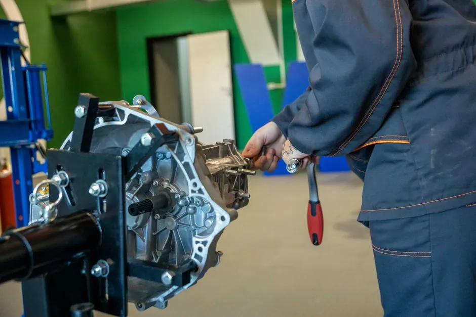
A ball spline combines a grooved shaft, recirculating balls, and a spline nut to carry axial load and transmit torque, with some rotary versions rated above 10 times the load of a same-diameter linear bushing [S1][S2].
The practical distinction is system architecture: a ball spline is an integrated linear guide and torque-transmitting coupling, while a splined shaft supported by a separate linear bearing uses two mechanically distinct functions and adds mounting, alignment, and envelope requirements [S1][S3][S5].
What Each Configuration Actually Does
A conventional ball spline has 3 basic elements: a grooved shaft, a spline nut, and ball bearings. The shaft grooves prevent the nut from freely rotating, allowing torque to pass in either direction between shaft and nut, while the circulating elements provide low-friction axial travel [S5].
A ball spline is therefore not merely a linear bearing. It can guide axial movement, resist radial displacement caused by torque, and transmit torsional load. Rotary ball splines add a rotating element outside the spline nut, using angular-contact bearings, crossed rollers, or gears to combine rotary and linear motion [S1][S3][S5].
By contrast, a conventional splined shaft uses machined splines to connect mechanically to its mating component, while a separate linear bearing supports and guides that shaft. If the spline is intended to transmit torque rather than merely provide rotational guidance, a keyed or splined connection and its bearing must be specified as a combined load path. The published ball-spline literature does not establish a universal load advantage for every separately supported splined-shaft arrangement, so capacity must be compared using manufacturer ratings for the actual shaft, bearing, and connection.
Load Capacity, Torque, and Motion Performance
That comparison supports a compact design decision, but it is not a universal rating across manufacturers, materials, dimensions, or mounting directions. Request equivalent rated-load definitions, including radial, axial, and torsional cases, before treating the ratio as a specification.
Ball splines can operate at high speed under high torsional loads because rolling contact replaces sliding contact and the splines restrain rotation. Their claimed operating benefits include reduced friction, less wear, lower stick-slip, less seizure, and lower backlash than suitable sliding systems [S3]. Preload changes the result: higher preload tightens the balls in their grooves, increasing friction but improving rigidity, accuracy, and life, while an unpreloaded spline can exhibit angular backlash [S5].
For a separate linear bearing, the decisive limitation is usually the connection and support system rather than the shaft surface alone. A splined connection can carry torque, but torsional reactions pass into the bearing supports and structure, increasing the risk of shaft twist or angular deflection if the span and support arrangement are not sized correctly. A ball spline distributes the spline load along the engagement length and uses the shaft itself as the guide member [S6][S7].
Decision Matrix: Compactness, Integration, and Serviceability
On packaging, the ball spline usually wins for rotary-and-linear axes because one shaft can replace the dual-stacked, four-bearing arrangement described for separate shafts [S3]. On serviceability, the split arrangement wins when the bearing can be replaced without disturbing a machined spline, because a conventional linear bearing is a separable component while the ball spline nut is a matched rolling-element system [S1][S5].
On torsional rigidity, a ball spline is the stronger default because its grooved shaft and nut are designed to transmit torque directly. A separate arrangement offers more freedom to select bearing supports and shaft modifications, but every support, key, or spline becomes part of the torsional load path. On preload and accuracy, neither option is automatically superior: ball-spline preload must be selected deliberately, while a separate bearing, shaft diameter, support span, and connection clearance determine its actual behavior [S5].
Use a ball spline when one shaft must translate, rotate, or combine both functions, when envelope width is constrained, or when an integrated rotary nut reduces the number of interfaces. Use a splined shaft with a separate linear bearing when the design is primarily linear, the torque connection must remain conventional, or independent bearing replacement is more valuable than compact coaxial integration.
Where the Separate-Component Design Fits Better
A separate spline shaft and linear bearing is appropriate when the application requires one motion axis and the shaft is easier to manufacture, inspect, or modify than a grooved ball-spline shaft. It also fits modular machinery in which the bearing supplier, support housing, and shaft connection must be selected independently rather than as a matched spline-and-nut set [S1][S5].
The design must account for the radial support arrangement. If the spline nut is fixed and must rotate, an external radial bearing may be needed on the nut, increasing bulk and making the nut harder to adapt around different bearing sizes. A rotary ball spline incorporates a radial support bearing and can therefore be more compact than a standard spline nut with an added bearing [S5].
The separate approach is also the practical choice when the shaft must rotate without an integrated torque-transmitting spline nut, or when a key, keyed hub, or splined coupling must carry the torque. For key-based alternatives, the torsional and axial load ratings of the shaft key and hub must be checked separately from the linear-bearing rating.
Failure Modes, Alignment, and Preload
Three failure mechanisms deserve separate checks. First, angular backlash can arise when an unpreloaded spline nut and shaft are not tightly coupled; preload reduces this motion but increases rolling-element friction [S5]. Second, cantilevered loads increase shaft deflection and bearing reaction, so vertical axes and overhung tooling require greater stiffness than a basic axial-load comparison shows [S3].
Third, separate components create an alignment problem between the splined shaft and its linear bearing. The bearing controls shaft position, but the spline connection must still be aligned with the driven member. A ball spline reduces that interface count by combining the shaft, spline nut, and rolling elements, although its own shaft support and mounting errors still require control [S1][S3].
For rotary ball splines, select between angular-contact bearing and crossed-roller support technologies only after defining stroke length, velocity, applied load, mounting space, duty cycle, required life, dimensions, installation direction, environment, and accuracy [S5]. Angular-contact bearings provide a compact rotary nut arrangement, while crossed rollers provide line contact and greater rigidity, but the research does not supply a universal crossover load or speed table. Verify those limits from the selected model rather than generalizing.
Application Match: Robotics, Automation, and Machine Tools
Ball splines suit robotic wrists, rotating grippers, laboratory automation, and high-speed pick-and-place mechanisms where a wrist-like twist and axial movement occur on one axis [S3]. Thomson also identifies vertical strokes and cantilevered architectures as applications where the ball spline structure can extend stability beyond the load envelope of a typical robot mechanism [S3].
A separate spline shaft with a linear bearing is better suited to conventional linear stages, manually actuated assemblies, and equipment where the torque path is brief and independent bearing service has practical value. It is less compelling when the mechanism needs simultaneous rotary and linear motion, because combining a rotary nut, spline nut, and drive can recreate the component count that the integrated ball spline was intended to reduce [S1][S3].
For indexed rotary applications, use the dedicated ball spline selection criteria for a rotary index table to examine indexing accuracy, drive arrangement, and load cases before finalizing the architecture.
Sourcing and Verification Checklist
Request dimensional drawings, material grades, hardness, groove geometry, permissible load and torque, speed limit, life equation, lubrication method, preload class, mounting orientation, and accuracy data from the selected supplier. The research identifies shaft diameter, load, torque, speed, stroke, duty cycle, life, environment, and mounting space as core selection inputs [S2][S5].
Do not compare only catalog maximums. Apply the actual radial, axial, and torsional load cases to the selected model, then include support spacing, cantilever length, preload, duty cycle, and operating environment. For a ball spline, verify nut and shaft pairing, angular-contact or crossed-roller support details, and the manufacturer’s life equation. For a separate system, verify the bearing’s dynamic and static ratings, shaft deflection, spline or key capacity, and alignment tolerance.
The decision is straightforward when the requirement is one axis with independent bearing replacement, and when the requirement is a compact combined linear and rotary motion. Record the selected model’s rated load, speed, torque, preload, stroke, and allowable cantilever before release, because these are the traceable signals that determine whether the chosen architecture fits the machine.