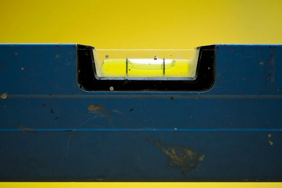
A hydrostatic level transmitter built on a ceramic capacitive cell (Al₂O₃ diaphragm, 0.01 mm electrode gap) trades raw sensitivity for corrosion immunity and high overload tolerance, while a piezoresistive silicon cell delivers higher millivolt-per-V psi sensitivity at lower unit cost but needs temperature compensation and media isolation [S1][S3][S5].
For a tank engineer the decision is rarely about which cell is "better" in the abstract, it is about which failure mode (overpressure spike, abrasive slurry, CIP chemical, thermal drift) would actually shut the loop first on that vessel [S2][S5].
What the Two Cells Actually Are
A ceramic capacitive cell uses an Al₂O₃ diaphragm as one plate of a capacitor; the second electrode sits 0.01 mm behind it, so applied pressure changes the gap and therefore the capacitance, which the on-board microprocessor then converts to a digital pressure reading [S1]. Endress+Hauser's Ceracore line ships the same architecture in 17.5 mm and 32.4 mm outer diameters, with standardized measuring ranges from 100 mbar up to 100 bar [S2].
A piezoresistive cell uses a silicon diaphragm with implanted or diffused resistors whose resistance changes under strain; the bridge output is then a millivolt signal proportional to pressure, typically requiring amplification and active temperature compensation [S5][S6]. The defining feature of the silicon variant is micro-pressure sensitivity; the defining feature of the ceramic variant is mechanical robustness [S3][S5].
How They Behave in a Hydrostatic Loop
Ceramic capacitive cells are characterized in vendor literature as tolerant of short-term overpressure conditions and stable across a wide temperature range, because the ceramic body itself has very low mechanical hysteresis compared with silicon [S3]. Overload resistance is specifically called out as a strength, alongside "outstanding long-term stability", in the Ceracore datasheet language [S2].
Piezoresistive silicon cells, by contrast, are described as highly sensitive and compact, with low unit cost, but the same sources flag temperature sensitivity and the need for compensation circuitry to hold accuracy over process swings [S5]. In a hydrostatic level application that means the silicon cell is the better choice where small head changes must be resolved on a short span (for example, 0-1 mwc on a small day tank), while the ceramic cell is the better choice where the loop has to survive water hammer, pump starts, or CIP shock [S3][S5].
Decision Matrix: Criteria, Numbers, and Edges

Lining the two options up against four decision criteria gives a quick engineering scorecard. On sensitivity (micro-pressure detection, small ΔC/ΔP or ΔR/ΔP) the piezoresistive cell wins; ceramic capacitive is described as "slightly less sensitive" in a head-to-head review, with the trade being stability [S5]. On overload tolerance, the ceramic cell is favored, with standardized ranges up to 100 bar and high overload resistance called out in the vendor spec [S2]. On media compatibility, ceramic Al₂O₃ is widely listed as corrosion resistant and "ideal for harsh cleaning conditions in the food and beverage industry", and is specified for water, wastewater, ballast, and aggressive chemical service; piezoresistive silicon almost always needs a stainless or elastomer isolation diaphragm plus oil fill in any media-touching application [S1][S2][S5]. On temperature behavior, ceramic cells are described as performing across a wide temperature range with minimal signal drift, while piezoresistive cells exhibit drift and require compensation circuits [S5].
A separate but useful envelope criterion is the cell's reference scheme: capacitive ceramic absolute-pressure cells can be supplied with a sealed reference vacuum on the order of 6 × 10⁻⁶ mbar inside the cell, giving permanently stable absolute readings without a vented reference line to atmosphere [S2]. That matters for open-tank hydrostatic service where gauge venting is awkward, and it matters even more for closed vessels where barometric compensation via a reference tube is impractical.
Selection Criteria by Tank and Service
Pick a ceramic capacitive cell when the tank is open or vented to atmosphere and the measured fluid is water, wastewater, a mild chemical, a slurry with abrasive fines, or a hygienic food/beverage product subject to CIP/SIP cleaning, and when the loop must tolerate pump-induced pressure transients without damage [S1][S2]. The ifm PY family is explicitly positioned for insulated tanks and "harsh cleaning conditions in the food and beverage industry", which maps directly to hydrostatic level on hygienic vessels [S1].
Real Use Cases in 2026 Plant Practice
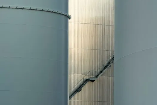
In environmental engineering, ceramic gauge pressure cells are specified for groundwater and wastewater level measurement, where long-term stability and resistance to humid, mildly corrosive atmospheres outweigh raw sensitivity [S2]. In shipbuilding, the same ceramic technology is used for level measurement of ballast and cargo tanks, a service defined by salt water, sloshing, and pressure spikes during ballasting [S2]. In construction, ceramic capacitive cells are used to detect early subsidence of buildings, tunnels, and other structures, which is essentially a long-baseline hydrostatic/geotechnical application where drift would be the dominant error source [S2].
For comparison, the piezoresistive silicon cell shows up at the other end of the spectrum: medical and laboratory equipment that needs to resolve very small pressure changes, and high-volume consumer or automotive pressure modules where unit cost dominates the bill of materials [S5]. Process engineers who try to use a bare piezoresistive cell in a slurry or CIP service typically add a heavy isolation diaphragm and fill oil, which then negates most of the cost and sensitivity advantage of the silicon element [S5].
Limitations, Failure Modes, and Integration Notes
Ceramic capacitive cells require more complex signal conditioning than a raw piezoresistive Wheatstone bridge, because the capacitance change has to be converted to a voltage and then digitized by an on-board microprocessor before any 4-20 mA, HART, or IO-Link output can be produced [S1][S7]. Vendors also note that the measuring cell assembly is the same across different product families, even when the outer body changes, which simplifies spares but means the cell itself is the long-term stability bottleneck, not the housing [S1].
Piezoresistive cells fail in three characteristic ways: temperature drift that exceeds the compensation circuit's correction envelope, media ingress if the isolation diaphragm is damaged or fatigued, and mechanical fatigue of the silicon diaphragm under repeated overpressure spikes [S5][S6]. In a hydrostatic level loop the dominant failure mode is usually thermal (a sunny outdoor tank, a steam-cleaned vessel) rather than electrical, so the ceramic cell's lower drift per °C tends to dominate total cost of ownership even at higher unit price [S5].
For engineers comparing a hydrostatic level transmitter head-to-head, the practical rule is: if the datasheet shows the cell family and the media is anything more aggressive than clean water or air, start with ceramic capacitive; if the span is under 1 mwc and the environment is benign, a piezoresistive cell with isolation diaphragm is acceptable. Capacitance-based variants are also covered in the capacitance level transmitter and capacitive sensor encyclopedia entries, which help when the same vendor offers both capacitive and magnetostrictive level transmitter options and the decision has to be made on a per-vessel basis [S1][S2].
Track the Ceracore USC30/USC70 datasheet revision and the ifm PY family firmware notes for changes in overload rating, temperature envelope, and IO-Link process-data mapping; also watch for any 2026 vendor announcements of piezoresistive modules with integrated digital temperature compensation aimed at outdoor hydrostatic service, which would shift the cost/robustness balance on small-span tanks.
Background reading: 2 Inch Expansion Anchor Use Frequency in Heavy Equipment Mounts.