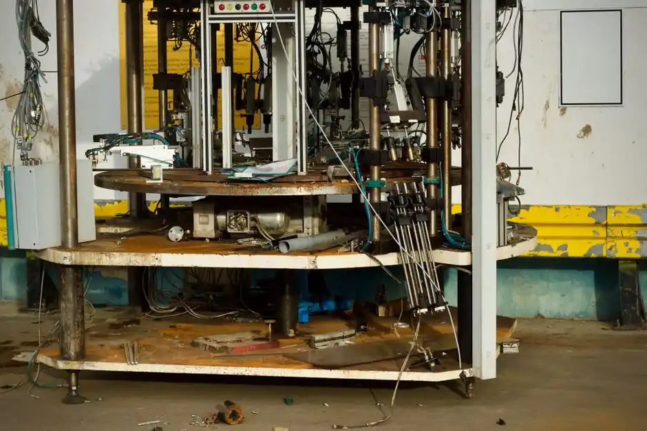
For standard screw-on caps, spindle cappers generally suit continuous high-speed lines, while chuck cappers provide tighter torque control for sensitive or specialty closures [S1][S3].
The decision is driven by closure geometry, bottle stability, required output, torque repeatability, and changeover frequency, with both machine types available in automatic and semi-automatic formats [S2][S3].
How Chuck and Spindle Cappers Apply Torque
A spindle capper uses multiple rotating disks to contact the sides of a cap and tighten it by friction as containers move continuously through the capping zone. This arrangement supports high-throughput packaging of standard screw caps and continuous-thread closures [S2][S3].
A chuck capper lowers a gripping head over the closure, rotates it onto the container finish, and disengages through a clutch after reaching the preset torque. The chuck then retracts and releases the container [S1].
The operating difference is consequential: spindle capping is continuous motion, while chuck capping is generally a stop-and-go process that requires each bottle to stop in an accurate position [S3].
Selection Criteria: Torque, Speed and Closure Type
Choose a chuck capper when applied torque must remain tightly controlled, the closure is sensitive to overtightening, or the cap requires a defined application method. Chuck systems can grip flat caps, while pump dispensers and trigger sprayers are better handled by spindle disks because a descending chuck may damage them.
Choose a spindle capper when the line runs standard plastic screw caps continuously and output matters more than the last increment of torque repeatability. Friction-driven spindle tightening can vary slightly between containers, and side contact may scuff softer or decorated caps [S2].
Flat caps are straightforward for a descending chuck, but pumps and trigger sprayers can be damaged when the chuck head comes down over them and are better handled by spindle disks. Side-contact spindle disks are often the safer choice for those closure shapes [S3].
Comparison by Application, Integration and Changeover
For a standard plastic screw cap on a stable container at high line speed, a spindle capper offers the better fit because bottles remain in motion and the disks can handle the closure without indexing interruption. This makes spindle capping the stronger candidate for food, beverage, household-cleaner, and some pharmaceutical lines [S2][S3].
Its stop-and-go sequence can improve positioning, while its clutch-controlled torque provides more direct control of closure load [S1][S3].
Chuck changeovers are the practical constraint. A standard chuck is intended for one cap size and a longer run at high speed, while a flex chuck can accommodate multiple cap sizes but adds setup complexity. Frequent size changes are therefore less suitable for a tightly configured chuck station [S5].
Automatic and semi-automatic implementations are available for both technologies. Spindle cappers are the more common automatic solution, while chuck cappers are widely used in tabletop, manual, and full-frame semi-automatic formats where an operator handles each cycle [S3].
Line Design and Bottle Stability
Very small containers can be difficult to stabilize on a power conveyor while spindle disks tighten the cap. A chuck station can use a screw or starwheel indexing system to locate each container at a fixed position before the head descends [S3].
A spindle capper normally does not require the container to stop, which can improve total line throughput when the upstream conveyor is stable and bottle spacing is controlled. The capping process itself, however, depends on friction between the disks and cap, making closure material, surface finish, and container presentation important variables [S2][S3].
An inline chuck capper uses one central capping head and is described as suitable for smaller or slower lines, whereas a rotary chuck capper uses multiple heads for larger or faster operations. Machine configuration must therefore be matched to the required number of bottles per minute rather than classified simply as chuck or spindle [S5].
Use Cases and Failure Modes

Use a spindle capper for continuous-thread caps that can be contacted safely on their sides, especially standard closures moving through a stable, high-speed conveyor. The main failure risks are incomplete tightening, side marking, and variation caused by inconsistent friction [S2].
Use a chuck capper where closure damage or seal inconsistency has a higher cost than a slower cycle. Its main failure risks are incorrect chuck-to-cap fit, excessive setup effort during size changes, damage from head contact, and poor bottle location if indexing is not correctly configured [S1][S3].
Neither machine can correct an unsuitable closure or finish. Cap dimensions, thread geometry, container stability, cap placement, and downstream seal requirements still need validation. The practical comparison is also discussed in Capping Machine Speed for High-Volume Production Lines.
Sourcing Trial and Production Validation
Specify the cap samples rather than describing them only by closure category. For the trial, document cap diameter, height, top geometry, material, finish, thread standard, target closure torque, acceptable variation, line speed, bottle dimensions, and changeover frequency. These inputs determine whether spindle disks can grip the cap safely and whether a chuck can descend without contacting vulnerable features [S1][S3].
For spindle trials, check tightening across the complete cap-size range, inspect sidewalls for scuffing, and verify seal performance because friction can vary between closures. For chuck trials, verify clutch disengagement, repeatability, indexing clearance, and the time required to change chuck tooling [S1][S2][S5].
Track bottles per minute, torque distribution, cap damage rate, miscap rate, seal rejects, changeover time, and operator interventions during acceptance. The final selection should follow verified output and closure quality, not machine category alone.
For high-speed standard screw caps, start with a spindle-capper trial; for controlled-torque or specialty closures, start with a chuck-capper trial, then release the machine choice against measured torque, damage and seal results.