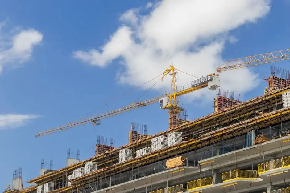
Hünnebeck SCF self-climbing formwork can take up and discharge forces up to a maximum vertical load of 150 kN per bracket [S1].
The rating applies to a defined system arrangement, not an isolated platform: climbing brackets transfer wall-formwork dead load and wind load through preset anchors, while operating conditions and configuration determine the safe speed [S3][S7].
Wind rating is a system limit, not a generic platform rating
Published climbing-formwork data cover two different decisions: whether the system may remain in service under wind and whether it may climb or be positioned at a particular exposure. Hünnebeck reports a very high vertical load capacity of up to 150 kN per bracket [S1].
That 208 km/h figure is not permission to work at 208 km/h. It describes a tested system capability, whereas PERI’s CB 240 instructions define a working-condition wind load of q = 0.25 kN/m² at vw = 72 km/h with the formwork retracted 75 cm or in its concreting position [S7]. Project-specific operating restrictions must remain with the engineered assembly.
A practical specification should therefore identify the system, load case, configuration, and permitted wind speed rather than state one universal “wind rating.” This distinction also matters when comparing climbing formwork with suspended access equipment designed for a different load path.
Bracket capacity and spacing control the wind envelope
Hünnebeck states that SCF self-climbing formwork is suitable for forming operations at heights of over 300 m [S1].
The vertical figure is not a wind pressure and must not be read as one. The 150 kN capacity covers forces taken up and discharged by the bracket during climbing and static conditions, while the influence width defines how much shuttered area contributes to that bracket arrangement [S1].
MEVA describes the load path clearly: climbing brackets are fixed to preset anchors, and these anchors transfer the wind load and dead load of the wall formwork and brackets [S3]. The spacing decision is consequently a structural decision involving formwork area, pressure, anchors, rails, brackets, and operating condition, not a value chosen from platform width alone.
Operating wind limits vary by configuration
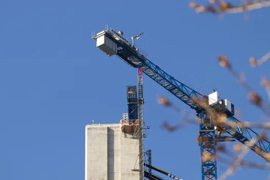
PERI Load Combination A specifies q = 0.25 kN/m² with a wind speed of 72 km/h for its stated working condition, including the formwork retracted 75 cm or in the concreting position [S7]. The document identifies the condition, so this value cannot be transferred unchanged to another bracket spacing, screen arrangement, or cycle state.
The wider project context must also separate climbing from working. By comparison, MEVA states that rail-guided climbing formwork remains anchored to the structure under prevailing weather conditions [S3].
PERI specifies a working wind load of q = 0.25 kN/m² at a wind speed of 72 km/h for the stated working configuration [S7]. Neither figure overrides the manufacturer’s instructions for a particular assembly.
Open screens reduce wind loading, but do not create a rating
EFCO describes edge-protection and self-climbing systems used in the construction of skyscrapers and high-rise buildings [S5]. This is a useful design measure because wind pressure on a solid face is transferred into the climbing platform and its anchors, while an open screen allows more airflow through the enclosure.
Open mesh does not eliminate wind forces, bracket uplift, lateral loads, or stability requirements. A finite-element study of climbing formwork installed at a bridge height of 100 m modeled wind loading and found bending effects more pronounced than other response characteristics [S2]. Dynamic analysis therefore belongs in the assessment when platform proportions, exposure, or operating behavior make a simple static check inadequate [S2].
For comparison with temporary work at height, the scaffolding selection process must consider the same chain: wind pressure, imposed load, anchorage, stability, and manufacturer-specific restrictions.
Hydraulic climbing changes the operating model
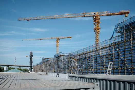
Hünnebeck SCF climbs step by step using an integrated hydraulic device without a crane, and one pump can operate up to 8 brackets simultaneously [S1]. That operating capacity does not remove the need to secure and stabilize the assembly during movement or to verify the wind condition for the selected cycle state.
MEVA identifies hydraulic rams as the lifting mechanism for the scaffold, formwork, and secondary formwork in self-climbing systems [S3]. A construction report describes automatic climbing formwork secured by 4 climbing cones against lateral loads such as wind [S8]. The number of anchors is therefore evidence of a connection arrangement, not a universal wind-speed certificate.
Owners planning repeated cycles should also coordinate wind procedures with climbing formwork crew size and lift cycle timing, since suspended work, suspension criteria, and climb authorization are distinct controls.
Engineering checks must include platform, anchors, and operating state
Hydraulic climbing formwork live-load combinations can include wind load, crane-platform construction load, and upper and lower operating-platform loads [S6]. A credible wind assessment should therefore preserve these simultaneous actions rather than check wind against the platform alone.
The reviewed evidence provides two usable specification anchors: Hünnebeck’s maximum vertical load capacity of 150 kN per bracket [S1] and PERI’s working wind load of q = 0.25 kN/m² at 72 km/h in its stated configuration [S7].
For procurement or lift planning, require the project-specific wind-load calculation, operating wind speeds by cycle state, exposed area and pressure assumptions, bracket spacing, anchor configuration, track and rail loads, and any governing manufacturer instruction. Keep the permitted work and climb speeds separate, and prohibit extrapolation from one brand’s test value to a different system configuration.