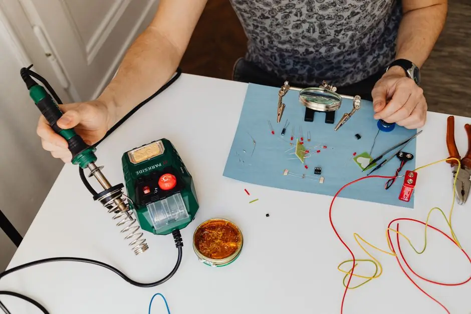
A common point ground is the single Earth Bonding Point (EBP) that ties the ESD mat, bench frame, wrist strap, and any conductive fixtures back to the building protective earth (PE), and ANSI/ESD S20.20 / IEC 61340-5-1 require that every ESD-protected element share that one potential [S2][S5].
The mechanism is potential equalisation, not current drainage: when the operator, mat, and component sit within the same millivolt window, no discharge event can fire across the gap [S5]. Eliminating multiple return paths also keeps ground loops from becoming ESD-event antennas in their own right [S1].
What the Common Point Ground Actually Is
An EBP is typically a low-profile terminal block with 10 mm banana jacks, 10 mm sockets, or 4 mm snap studs, hard-wired back to the building PE bar through a single cord [S4][S5]. Commercial products like the Static Care 15 ft common-point kit ship with a banana plug at the mat end and a separate adapter that picks up only the ground pin of a standard outlet, so the mat and the operator share one source [S3][S5].
Desco's catalog lists dedicated cords at 10 mm stud or 10 mm socket terminations, with and without series resistors, in standard 15 ft lengths, which keeps the bench wiring to a single, traceable run rather than a daisy chain [S4]. Elimstat's design notes push the same point: a dedicated ESD ground point, not a borrowed pipe or chassis screw, is the only clean way to bond the mat, frame, and wrist strap into one system [S1].
Standards That Govern the Bonding Topology
ANSI/ESD S20.20 and IEC 61340-5-1 both define the framework for an ESD Control Program, including the requirement that all elements in an EPA be bonded to a common point ground rather than individually to building steel [S2]. The Polish transposition PN-EN 61340-5-1 is cited in current integrator guidance as the operative standard for new European EPA builds [S5].
For personnel, the wrist-strap coiled cord must include a 1 MΩ resistor in series with the operator, which limits fault current and is one of the few hard numeric values that every standard agrees on [S5]. Joe's small-shop case study in In Compliance Magazine follows the same S20.20 plan structure: a documented ESD Plan, training records, compliance verification, and product qualification, all built around one common point ground buss [S2]. The grounding topology is identical in both standards; what changes is the audit trail.
Wiring the Station: A Hardware-Level Map
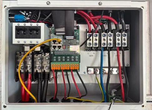
Step 1 is verifying that the outlet's third pin is a real PE, not a bootleg ground, and step 2 is mounting the EBP so it picks up only the PE conductor through a dedicated adapter [S5]. Step 3 bonds the conductive table frame to the EBP with a cord whose termination matches the frame stud (commonly 10 mm snap or ring terminal), and step 4 repeats the run for the bench mat so the mat and the frame share the EBP, not each other [S3][S5].
Step 5 lands the wrist strap into the EBP (or a jack that is itself bonded to the EBP), and step 6 measures continuity end-to-end with a constant-voltage low-current ohmmeter or a wrist-strap / workstation combo tester, which is the daily compliance-verification check called out under S20.20 [S2][S5]. The 30 cm clearance rule for non-ESD equipment on shelves above the mat is a S20.20 field-strength mitigation: keep charged insulators away from the discharge gap, and you do not have to ground the shelf at all [S2].
Component Options: Resistor vs No-Resistor, Stud vs Socket
Common point ground cords are sold with and without a 1 MΩ series resistor, and the choice is not stylistic. Wrist-strap cords always carry the 1 MΩ resistor for operator safety; mat and frame bonding cords usually do not, because the mat is already a high-resistance dissipative surface and the frame is a hard ground reference [S4][S5].
Termination style drives installation time: 10 mm stud fits the EBP and most North American bench hardware, 10 mm socket accepts a 10 mm plug from a mat snap, and 4 mm banana plugs show up on European Wrist straps and some meter leads [S4]. The comparison below is the decision an integrator actually makes at the bench:
<strong>Option A, 10 mm stud, no resistor:</strong> cheapest, used for mat-to-EBP or frame-to-EBP on a hard-grounded bench; ~$18.77 list for a 15 ft cord [S4]. <strong>Option B, 10 mm socket, no resistor:</strong> same use, but the EBP side accepts a 10 mm plug rather than a stud, which is helpful when the EBP is already populated with ring-terminal grounds [S4]. <strong>Option C, integrated kit with banana plug + snap:</strong> sold as a complete consumer-grade assembly (Static Care, ~$19.55) for one-operator mat-and-wrist-strap stations where sourcing individual cords is overkill [S3]. <strong>Option D, factory-integrated bench ground:</strong> an RTWORK-style professional bench with a factory-bonded frame and pre-installed EBP stud, which removes the daisy-chain wiring entirely and shortens compliance verification [S5].
Who Needs a Common Point Ground, and Who Can Skip It

Any workstation that handles ESDS (ESD-sensitive) components inside an EPA needs a common point ground: prototype benches, repair shops, surface-mount lines, and field-service kits included [S2]. The standard explicitly covers organizations that manufacture, process, assemble, install, package, or otherwise handle ESDS parts, so the size of the company is irrelevant; the activity is what qualifies the workstation [S2].
The one configuration that can defer the floor mat is a single seated operator at a grounded workbench who never stands up at the bench, because the wrist strap already equalises them through the EBP [S2]. A two-person cell, a standing inspection station, or any cell where the operator moves between grounded and ungrounded references needs the floor mat, ESD footwear, and a second EBP branch to keep the operator at the same potential as the bench [S2][S5]. For the wiring-adjacent trades, the same equipotential logic shows up in PTFE vs graphite braided packing: a single, traceable bonding path beats a star of half-grounded connections every time.
Common Failure Modes and Compliance-Verification Traps
The most common field failure is not a broken wire but a bootleg ground: a three-to-two adapter, a painted chassis bolt, or a water pipe used as the PE reference, which the integrator guidance calls out as an explicit no-go [S5]. The second failure mode is daisy-chaining, where the mat is bonded to the frame and the frame is bonded to the EBP, so a single loose snap breaks the mat path silently; S20.20 wants each dissipative element bonded directly to the EBP, not in series [S1][S5].
The third trap is using a low-resistance cord (under 1 MΩ) on the operator path, which removes the current-limit that protects the wearer during a fault to mains voltage; the wrist-strap cord is the only cord in the system that is supposed to carry that resistor [S5]. Daily verification with a wrist-strap / workstation combo tester, plus periodic surface-resistance checks on the mat (typically 10^6 to 10^9 Ω for dissipative mats, per IEC 61340-5-1 ranges cited in current integrator guidance [S5]) is what catches all three failure modes before a board does. For process engineers who also spec controls hardware, the same idea of a single low-impedance reference shows up in any PLC cabinet: one PE bar, one star ground, every I/O module bonded back to the same point, so a noisy input cannot inject voltage into a quiet analog PLC channel.
Sourcing, Standards, and Trackable Signals

Two part numbers anchor the North American catalog: Desco 09825 (10 mm stud, no resistor, 15 ft) and Desco 09820 (10 mm socket, no resistor), both listed on the live Desco Industries catalog page as of the source crawl [S4]. The Static Care B09B2NVK5R kit on Amazon is the off-the-shelf equivalent for small shops, listed at $19.55 with Prime delivery, which is a useful price-floor reference for low-volume orders [S3].
Standards to cite on a drawing or audit checklist: ANSI/ESD S20.20 (program-level, US), IEC 61340-5-1 (program-level, international, transposed in EU as PN-EN 61340-5-1), and the 1 MΩ operator-resistance figure from the wrist-strap cord spec called out in current integrator guidance [S5]. Trackable signals to watch over the next quarter: any revision to the IEC 61340-5-1 resistance-band tables (current dissipative mat range 10^6 to 10^9 Ω as cited in [S5]), and any change to the S20.20 footwear / flooring resistance limits, which the Joe's-garage case study notes are the next refinement once a second operator is added [S2]. For engineers who also touch instrumentation, the equipotential-bonding principle behind the EBP is the same one that keeps a pressure transmitter shield drain bonded at one end only, to stop ground loops from showing up as drift on a 4-20 mA loop.
Spec-level background on the components involved: earth ground tester.
