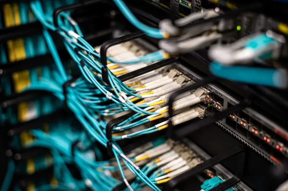
Control cable compatibility with a cycle-time specification is decided by four measurable gates, not by the cable catalog number: ampacity under the planned duty cycle, conductor flex endurance, bend-radius margin in the actual routing, and shielding/protocol performance at the cycle frequency of the connected control system.
For any actuator-driven application the duty cycle is computed as DC% = (t on / (t on + t off)) × 100, and total cycle time T cycle = t on + t off, with N = 3600 / T cycle cycles per hour; heat generation H scales with DC% × load factor, which is the physical link between cycle-time and cable temperature rise [S3]. The cable you select must keep its conductor below the insulation's rated temperature when driven at the worst-case DC% the machine will see in production, not the average.
Ampacity Under the Real Duty Cycle, Not the Catalog Number
A 14 AWG copper conductor in PVC insulation (commonly rated 600 V, 75°C) is typically derated from its 15-20 A table value down to roughly 12-15 A in a 30°C ambient, and further by an adjustment factor when bundled with other circuits, so a continuous-load application that draws 14 A in steady state forces the specifier to either move to 12 AWG or to a 90°C insulation that recovers usable ampacity at the higher conductor temperature.
Duty cycle derating, when published by the cable manufacturer, is expressed as a multiplier on continuous ampacity: 80% DC% rated conductors are often marked for 100% of the continuous table value, while 50% DC% applications can accept a 1.1-1.25× boost because the conductor has time to shed heat between pulses, provided the off-time is long enough relative to the thermal time constant of the insulation system [S3].
The pin-configuration gate applies even before ampacity. Jimmy Jib crane control cables, for example, use dedicated pin maps for head/pan/tilt/zoom/focus/iris functions; mismatched pinouts between cable and controller is the single most common field failure mode, ahead of any electrical rating issue [S2]. The same logic applies to industrial harnesses: a control cable that is electrically over-spec but pin-mismatched will not energise the load.
Flex Endurance vs Cycle Count: Match the Geometry, Not the Brochure
Cable flex life is rated in cycles to failure, typically 1×10^6 to 300×10^6 cycles for energy-chain (drag-chain) rated multi-conductor cables, with the rating valid only when the bend radius stays at or above the manufacturer's minimum, usually 7.5× to 10× the outer diameter for dynamic energy-chain use, and 4× OD for static routing. [S3]
For a machine spec'd at 60 cycles/hour (T cycle = 60 s) running 16 h/day, 250 days/year, that is 60 × 16 × 250 = 240,000 cycles per year, so a 10×10^6 cycle cable gives roughly 40 years of theoretical life, but only if bend radius, temperature, and acceleration profile are inside the test envelope; in practice, drag-chain ratings fall sharply when the radius is undersized or when the chain travels at >5 m/s, which is why a cable drag chain compatibility audit matters as much as the cable datasheet.
For applications such as broadcast camera cranes, where the control cable is hand-routed through a jib arm and flexed hundreds of times per shoot, the failure mode is jacket abrasion and conductor fatigue at the bend transition, so a polyurethane (PUR) or TPE outer jacket is preferred over PVC because PUR holds its durometer across the typical -20°C to +80°C operating window that broadcast and outdoor stages see [S2].
Thermal Derating: Why 25% DC% Is Not "1/4 the Heat"
The heat-generation factor H scales as H ∝ DC% × load factor, but the steady-state conductor temperature is set by the thermal time constant of the insulation/conductor system, which is on the order of 5-15 minutes for typical 14-18 AWG PVC-jacketed control cables; an actuator that runs 15 s on / 45 s off (25% DC%, N = 60/h) reaches a much lower peak temperature than one that runs 60 s on / 60 s off at 50% DC%, because the shorter pulse does not let the conductor reach thermal equilibrium [S3].
Specifying purely on average current is the classic mistake: a 25% DC% load with 40 A peaks delivers the same average power as a continuous 10 A load, but the peak current is what sets voltage drop and instantaneous conductor heating, so both the I²R copper loss calculation and the insulation temperature limit must be checked at the peak.
For higher-cycle or higher-temperature environments, cross-linked polyethylene (XLPE) or silicone insulation raises the continuous conductor rating from 75°C to 90°C or 150°C respectively, recovering 10-20% ampacity at the cost of flexibility; this is the trade-off that a process control panel builder weighs against jacket material and connector thermal limits.
Signal Integrity Under Cycling: Shielding, Protocol, and Ground Loops
Digital control protocols such as PROFIBUS, Foundation Fieldbus, and Ethernet-APL have specific cable requirements (characteristic impedance, capacitance, shield coverage) that are independent of the power conductors, so a hybrid power-and-signal cable must be specified to the strictest of the bundled limits, and the shield must be terminated at one end only (low-frequency analog) or both ends with a low-impedance bond (high-frequency digital) to avoid ground loops that show up as intermittent faults only when the cycle frequency approaches the loop's resonant peak. [S1]
Real-time cycle-slip detection, originally developed for GPS carrier-phase quality control, uses the Geometry-free and Melbourne-Wübbena linear combinations plus filter techniques to detect single-cycle slips in real time, and the same statistical approach is now applied to industrial encoder and resolver feedback cables to catch one-count errors that would otherwise be invisible to a simple PLC high-speed counter but would cause a cycle-time deviation in closed-loop motion.
Application Cut: Who the Cycle-Time Cable Spec Is For, and Who It Is Not
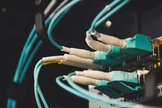
This specification discipline is built for machine builders, panel integrators, and end-user maintenance engineers who must justify a cable choice against a documented cycle count, ambient temperature, and protocol requirement, and it is not a fit for one-off low-cycle installations (manual valves, fixed lighting) where a general-purpose cable is sufficient.
For high-cycle servo and stepper motion (cycle times under 100 ms, frequencies above 10 Hz), the cable must be a dedicated flex-rated energy-chain type with a tested cycle rating, not a generic "stranded" multi-conductor; for low-speed instrumentation where the cycle time is in seconds and the count is below 10,000/year, a static-rated cable with adequate derating is more cost-effective and easier to terminate.
Verification Checklist Before the Cable Hits the Reel
Five numbers must be on the purchase order before the cable is cut: (1) the planned DC% at full production, (2) the peak current per conductor, (3) the minimum static and dynamic bend radius, (4) the cycle count in the machine's life (cycles per hour × hours per day × days per year × design years), and (5) the protocol and shielding requirement for any signal pair in the bundle. If any of these five is missing, the cable is being guessed, not specified. [S3]