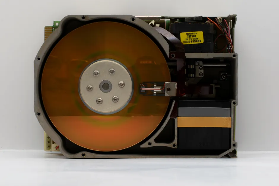
A self-aligning bearing tolerates roughly 1.5-3.0° of static angular misalignment between shaft and housing, but incremental encoders with sub-arc-minute accuracy budgets can see their error envelope blown by even that small skew, so the two subsystems are compatible only when mechanically and electrically aligned to a common spec [S1][S3].
Across industrial servo installations, the failure mode is rarely the bearing itself; it is the feedback loop losing accuracy because the shaft-to-encoder stack was sized without checking radial runout, axial play, and coupling stiffness against the encoder's stated accuracy class, with operating speeds commonly ranging from 500 rpm in paper-line rollers to 12,000 rpm in servo spindles [S3][S4].
Where self-aligning bearings fit in an encoder feedback loop
Self-aligning bearings, whether self-aligning bearing ball or roller types, are designed to absorb shaft deflection and mounting-face errors that would otherwise preload a rigid ball bearing and drive it toward premature brinelling, with the spherical outer race path giving the rolling element assembly a few degrees of freedom relative to the housing bore [S1][S2].
In a feedback-equipped drive, the encoder sits downstream of that bearing on the same shaft or on a through-shaft stub, so any axial float or angular drift the bearing absorbs translates directly into the encoder's airgap, codewheel position, or grating alignment, with magnetic encoders using Hall or magnetoresistive elements rated for 5-30 V supply and quadrature outputs at 90° phase offset [S3].
The practical install uses a self-aligning bearing on the non-driven end to soak up thermal growth and assembly stack-up, while the encoder end is referenced off a precision ball bearing with ABEC-5 or tighter tolerance to keep the feedback axis geometrically stable, a pattern engineers describe as "compliant inboard, stiff outboard" [S1].
Encoder feedback protocols and what they demand of the bearing stack
Magnetic encoders output two channels A and B phase-shifted 90° plus an index Z, and absolute variants retain shaft position across power cycles, which means the bearing's repeatability after power-off rotation matters more than its absolute radial play [S3].
Incremental quadrature decoding depends on clean edge transitions, so a rotary encoder mounted on a shaft with 0.05 mm of axial play from a self-aligning bearing can produce jitter that looks like a noise-floor problem but is actually mechanical, and the fix is rarely more shielding [S3][S4].
For linear stages using a linear encoder scale, the bearing carriage's straightness error feeds straight into the Abbe offset, and self-aligning bearings on a long screw-driven axis do not correct that; they only hide it until thermal load ramps up, after which the feedback shows a position-dependent error curve that no firmware gain can flatten [S3].
Compatibility gates: mechanical, electrical, and protocol
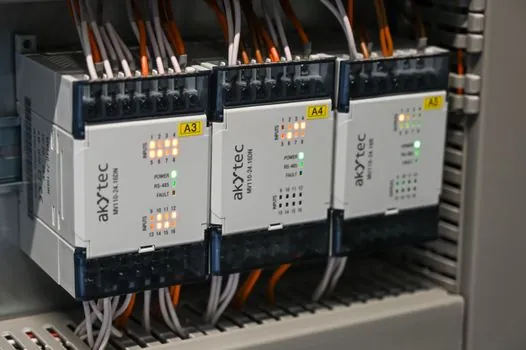
The mechanical gate is the easiest to check on paper: the bearing's allowable misalignment (typically 1.5-3.0° static for self-aligning ball, 0.5-2.0° for self-aligning roller) must be greater than the maximum combined shaft-to-housing angularity from manufacturing tolerances, thermal expansion, and load deflection, and the encoder's stated mounting tolerance must be tighter than whatever misalignment remains after the bearing seats [S1].
The electrical gate is the encoder supply and output level, with 5-30 V DC being the common industrial range for magnetic types, push-pull or line-driver outputs for long cable runs, and a clear separation between the 4-20 mA analog world of process transmitters and the digital pulse train of a servo feedback channel, a confusion that has burned more than one commissioning team [S3][S4].
The protocol gate is which bus or interface the encoder speaks: MODBUS, CANopen, and PROFIBUS are the three common industrial buses, each with its own cabling, addressing, and termination rules, and the bearing has no opinion on this, but the cable routing does, since a self-aligning bearing's housing usually rotates with the driven machine and the encoder pigtail must survive that rotation without inducing EMC into adjacent analog lines [S3].
Where the pair works and where it does not
The pair works well on conveyor drivetrains, mixer shafts, and fan pillow blocks where the shaft is long, the load is heavy, and the feedback encoder is a low-resolution speed sensor, with the self-aligning bearing soaking up frame distortion and the encoder just counting pulses for a VFD, a configuration that rarely hits the feedback accuracy ceiling [S1][S3].
The pair struggles on CNC spindles, robotic joint modules, and precision index tables where the encoder resolution is 20-bit or higher and the feedback error budget is single-digit arc-seconds, because a self-aligning bearing's permissible play exceeds the encoder's linearity spec by an order of magnitude, and a preloaded angular-contact pair referenced to the encoder mount is the correct call there [S3][S4].
A related pattern is documented in the Pulp and Paper Roller Bearing Selection spec map, where self-aligning bearings carry the dryer and felt rolls while encoders on those rolls feed tension control loops, and the alignment discipline is set by the feedback resolution, not the bearing catalog [S1].
Failure modes that pass a datasheet check but fail on site
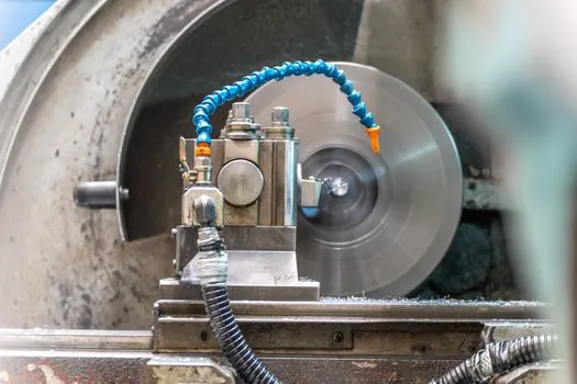
Shaft currents discharged through the encoder bearings are a classic site-failure mode: a VFD-driven motor with ungrounded bearing housings lets common-mode voltage discharge through the encoder's internal bearings, pitting them within months and corrupting the feedback signal well before the mechanical self-aligning bearing shows any wear, a pattern that has been written up across servo-drive service bulletins for over a decade [S3][S4].
Thermal growth of a long shaft supported by a self-aligning bearing on one end and a fixed ball bearing on the encoder end can shift the encoder's zero by tens of arc-minutes over a 60 °C warm-up, which the controller interprets as a position error and tries to correct via trim moves, loading the bearing until the self-aligning feature is operating near its angular limit and the feedback loop is fighting its own mechanics [S1][S3].
Cable flexing at the encoder pigtail is the third common site failure, especially on through-shaft hollow-bore encoder mounts where the cable must pass through the rotating assembly, and the cure is a 10-12 mm minimum bend radius, strain relief at the grommet, and a cable rated for 5-10 million torsion cycles, none of which appear on the bearing datasheet but all of which decide whether the feedback loop survives a year of production [S3].
Standards, sourcing, and what to demand from suppliers
Bearing dimensional standards govern interchangeability: the boundary dimensions for self-aligning ball bearings are set by ISO 15, with internal clearance classes C2, C0, C3, C4, and C5 defined under ISO 5753, and the encoder's required shaft and bore tolerances have to fall inside the bearing's actual achieved fits, not the catalog nominal, especially on adapter-sleeve mounted units [S1].
Encoder accuracy is normally classified per the manufacturer's datasheet into cycles per revolution (CPR), lines per revolution, or bits of resolution, with a stated accuracy in arc-minutes or arc-seconds, and the bearing's contribution to the error budget is the residual runout after assembly, which a proper acceptance test should measure with a dial indicator at the encoder mounting surface, not at the bearing housing [S3].
Sourcing discipline for both ends of the loop: demand the bearing's actual mounted clearance, not the class, and the encoder's accuracy grade, not its resolution, and verify the cable spec against the real routing path; for a packaged review of bearing certification gates on automated cells, the Ball bearing certification checklist for robotic transfer cells walkthrough is a useful adjacent read because it treats the encoder feedback loop as a certification gate rather than an accessory [S1][S3].
Two trackable signals to watch: the share of servo motor orders shipping with integrated absolute multi-turn encoders versus add-on modular encoders, since the integrated form factor eliminates one stack-up interface; and the adoption of single-cable servo technology (power plus feedback on one hybrid cable), which removes the encoder pigtail flex failure mode but pushes the EMC burden back into the drive and the bearing grounding scheme [S3][S4].