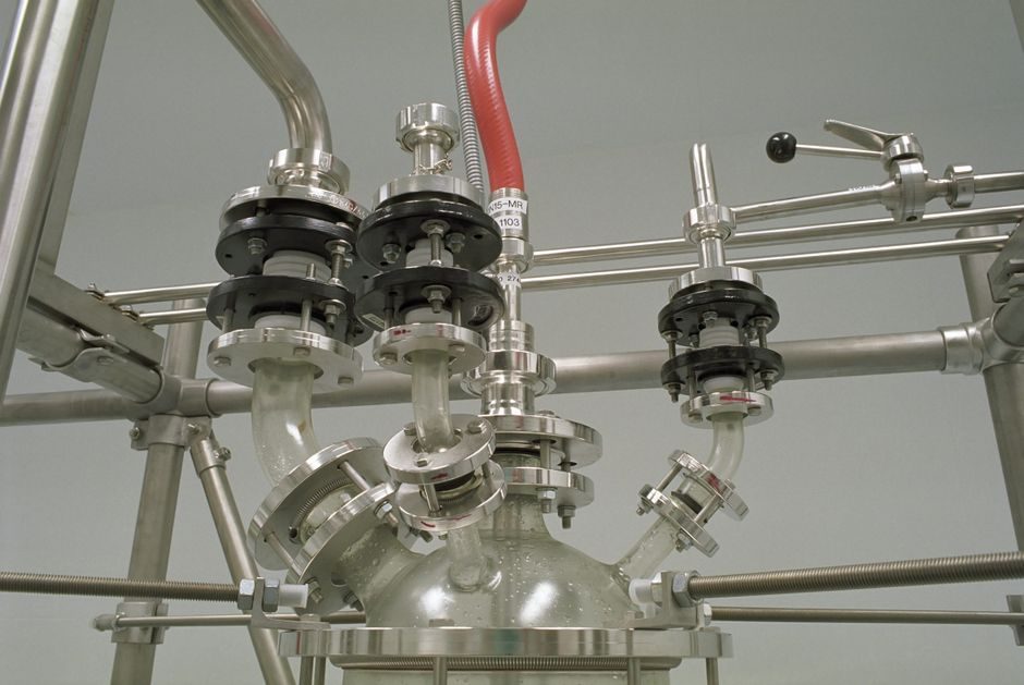
ISA-75.01.01 and IEC 60534 series govern control-valve sizing; the governing equation Q = N1·Cv·√(ΔP/ρ) (liquid) ties required flow to a Cv, then to a catalogued body/trim combination [S1][S3].
Selection spans five coupled decisions: body style, trim characteristic, actuator type, positioner protocol, and failure mode — each verified against process ΔP, temperature, and corrosion data before a part number is cut [S3].
Cv/Kv Sizing Math and Sizing-Software Stack
Liquid sizing uses Cv = Q·√(G/ΔP) where Q is gpm, G specific gravity, ΔP psi across the valve; metric sizing uses Kv = Q·√(ρ/ΔP) in m³/h, bar, kg/m³ — Kv ≈ 0.865·Cv at the same duty point, and vendors publish both so a US-built Cv curve can be checked against a EU-drafted Kv schedule without unit-conversion drift [S3]. Engineering Toolbox lists Cv calculators for liquids, gases, steam, and a Cv-vs-Kv conversion page to keep the two units aligned on the same datasheet [S3].
ISA-75.24 sits one layer above Cv math: it scopes the force-balance equations for pneumatic, hydraulic, and electric actuators covering piston area, effective diaphragm area, and spring rate so the bench stroke and supply pressure can be matched to the unbalanced forces the trim develops at shut-off [S1]. Bespoke sizing programs (Millstream, Valve Sizing Program) package those ISA equations behind branded catalogs so a quoter can run a full spec sheet — line size, Cv, characteristic, actuator bench, travel, air consumption — in one pass [S4][S6].
Body, Trim, and Characteristic-Curve Selection
Equal-percentage trim is the default for processes with high turndown because the small opening at low flow delivers a controllable % change per % stem move, while linear trim suits level loops where the controller expects a near-straight flow-vs-stem relation; double-seated or contoured plug trim is used where the inherent curve of a single-port equal-% body is too aggressive [S3]. For a deeper look at how these characteristic choices interact with the rest of the control valve trim, cross-reference the body/trim/positioner pages in our encyclopedia.
Ball, butterfly, globe, and segment-ball bodies dominate process plants; ball and butterfly in the 2″–24″ range are widely used for low-pressure-drop isolation and throttling on water and air, while globe bodies are specified for tight shutoff (Class IV–VI) and high-pressure-drop hydrocarbon services, and a typical butterfly delivers a Cv roughly 1.5–3× a same-size globe at full opening but loses authority at small openings [S3]. Material selection is driven by corrosion charts, with cast carbon steel per ASTM A216 for non-corrosive duties and 316SS or alloy trim for acidic or chloride service [S3].
Cavitation, Flashing, Noise, and Leakage Class
Cavitation index σ = (P1 − Pv)/(P1 − P2) below roughly 0.5 indicates incipient cavitation, and multi-stage trim or anti-cavitation cages are specified when ΔP approaches the choked-flow limit; for high-temperature hydrocarbon let-down, flashing downstream of the vena contracta is mitigated by hard-facing and downstream cage geometry [S3]. For linear motion components downstream of a control station, multi-stage trim cuts the radiated sound pressure level by typically 10–20 dB(A) versus a single-stage cage at the same Cv.
Safety-relief devices follow a parallel track: the ScienceDirect SRV chapter reiterates that a pressure-relief valve must be selected only with full knowledge of relieving requirements, connecting piping reaction forces, and the local code (ASME BPVC Section I/VIII, PED 2014/68/EU) before a set pressure is named [S2].
Actuator, Positioner, and Failure-Mode Match
Spring-return diaphragm actuators cover roughly 80% of throttling duties at 3–15 psig signal because the spring sets a defined fail-safe direction; piston actuators with higher bench thrust are used for large butterfly and ball bodies where diaphragm thrust is insufficient, and electric actuators are specified where instrument air is unavailable or where partial-stroke tests for SIL loops are required [S1][S3]. The OMEGA technical reference frames this as a structured pick — signal type, supply, fail action, then body — and notes pneumatic spring-return as the default for general process throttling [S5].
Positioners now run HART 7, Foundation Fieldbus, PROFIBUS PA, or IO-Link, and partial-stroke test routines embedded in smart positioners satisfy SIL-2/3 proof-test intervals without a full shutdown — but HART remains an FSK layer over 4-20 mA, not a drop-in replacement for a Foundation Fieldbus segment [S3]. Fail action is named per convention: fail-closed (FC) on heating and cooling water, fail-open (FO) on cooling-water bypass and on fired-heater excess-air dampers, fail-last (FL) on critical column reflux where a hard fail would dry the trays [S3]. For two-hand control consoles, the same spring/bench logic is wrapped in a permissive interlock so the operator cannot command a stroke without a second confirmed input.
Series/Parallel Piping, Authority, and Where NOT to Use
Valve authority β = ΔP_valve / ΔP_system should land in the 0.3–0.7 band; below 0.3 the loop loses controllability and a bigger body (or a re-routed pump head) is the right answer, above 0.7 the valve is throttling against itself and trim erosion follows — and Cv for valves in series combines as 1/Cv_total = Σ(1/Cv_i), while parallel valves add Cv values directly [S3].
Control valves are NOT a substitute for safety relief on over-pressure scenarios — even a fail-closed control valve cannot be relied on for Section VIII protection, and ISA-75.24 sizing equations assume the valve is in the modulating band, not at sustained shut-off against full pump head [S1][S2]. For crossed roller guide tables on linear-positioner feedback linkage, the same force-balance and travel-budget discipline applies, and any reading outside the 0.3–0.7 authority band is a red flag that the upstream pipe spec, not the trim curve, needs rework [S3].
Procurement and Standards Checklist
Specifying engineers should freeze: Cv/Kv at normal and maximum flow, allowable ΔP, body and trim material per ASTM grade, characteristic (linear / equal-% / modified), leakage class per FCI 70-2, actuator type and bench, positioner protocol, fail action, and the applicable NACE MR0175 clause if the service is sour (H₂S partial pressure > 0.0003 MPa) [S1][S3]. Sizing software from Millstream or Valve Sizing Program prints a full data sheet to lock those fields, and the ISA-75.24 force-balance method is invoked when the seat ΔP or shut-off load pushes beyond a standard catalog curve [S4][S6].
Trackable signals for follow-up: ISA-75.24 next-committee work item on hydraulic actuator force balance (S1), IEC 60534-8 (noise) laboratory revision, and the control cable routing guidance update for Foundation Fieldbus segment spurs in hazardous areas [S1][S3]. For buyers cross-referencing a lux meter selection procurement workflow, the same spec-sheet gating logic — duty, accuracy, protocol, certification — applies unchanged to a control-valve RFQ [S3].