
Ground bearing pressure for a crawler crane drops in inverse proportion to track pad width when total operating weight is held constant: doubling the shoe width from 760 mm to 1520 mm halves the calculated pressure, the same arithmetic that takes a 100-ton lift from roughly 100 kN/m² to about 50 kN/m² on identical contact length [S3]. Below 100 kN/m² the soil is generally suitable as-found, 100 to 200 kN/m² requires ground improvement or crane mats, and anything above 200 kN/m² demands engineered mats plus a geotechnical assessment [S3].
The trade-off is not free: wider shoes add un-sprung mass, raise transport width, and can exceed roadable dimensions without a removable track frame. For a site engineer the real question is what minimum contact area keeps demand below the soil's allowable capacity, which is where OSHA 1926.1402 (firm, drained, graded ground that meets manufacturer support specs) and the controlling entity's duty to disclose voids, tanks, and utilities become binding [S1]. The mechanics of the calculation, the failure modes, and the standard thresholds are detailed below for the typical 50 to 300-ton lattice-boom crawler used on industrial and infrastructure work.
The two pressures on opposite sides of the equation
Ground bearing pressure is the demand: total crane load (machine, counterweights, rigging, lifted load) divided by total track contact area, with units of kN/m², psi, or tons per square meter [S3]. Soil bearing capacity is the supply: the maximum pressure the ground resists before deforming, varying with soil type, moisture, compaction, and what lies beneath [S1]. A safe setup keeps demand below supply; if demand exceeds supply the failure mode is well documented, including outrigger punch-through on mobile cranes, uneven settlement, and tip events [S1].
Crawler cranes distribute load through long steel tracks, which already gives them a lower bearing pressure than outrigger-supported mobile cranes of equal capacity, yet pressure concentration still occurs when the boom slews over a track corner, when track pads are damaged, when mats are uneven, and when subgrade compaction is poor [S3]. A crawler crane's track shoe width and ground bearing pressure relationship is the single biggest design lever the operator controls in the field, before any mat is laid.
The arithmetic, plus a worked 100-ton example
The base formula is total crane load in kN divided by total track contact area in m² [S3]. For a typical 100-ton crawler with 760 mm shoes, 4.6 m ground contact length per track, and two tracks, the contact area is roughly 7.0 m². With an 800 kN combined operating weight and lifted load, average pressure lands near 114 kN/m², which is already inside the 100 to 200 kN/m² band that triggers a mat decision [S3].
Replace 760 mm shoes with 1100 mm shoes and the area jumps to about 10.1 m², dropping pressure to roughly 79 kN/m² and clearing the 100 kN/m² threshold on compact soil. Push to 1520 mm shoes and the area reaches 14.0 m², halving the original 760 mm figure to about 57 kN/m² [S3]. For a one-million-pound lift class, the same scaling applies, and the practical question becomes how wide the track can go before roadable-width limits or counterweight packaging stop the gain.
For a soil-side check, the pressure measurement convention used here (force per unit area) is identical to the kN/m² output that a pressure gauge would read on a hydraulic jack, which is why engineers familiar with hydraulic load charts can read ground pressure directly off a manufacturer data plate. The CICA / CANZ guidance frames the principle as: "Crane stability often depends on the integrity of the ground on which it stands" [S1].
Decision matrix: pad width, mat, or geotechnical hold

Three soil classes and three pad-width options line up as the field decision a lift planner makes. Soft clay at 25 kN/m² allowable capacity forces engineered mats for any crawler above about 50 kN/m², and even a 1520 mm shoe will not bring a 100-ton rig into the safe band on its own [S3]. Loose sand and backfill typically allow 50 to 100 kN/m², so a 1100 mm shoe with standard timber mats is the common choice. Compact granular fill at 150 to 300 kN/m² will accept a 760 mm shoe with no mat for most lifts, while solid rock above 600 kN/m² removes the mat question entirely [S3].
Track-pad geometry also shifts the failure geometry. The traditional assumption is uniform pressure under a rectangular equivalent footing of width B', but combined-loading research shows that real peak pressure under a track corner during a slewed lift can run significantly above the average, which is why the "peak ground pressure" line on a calculator output is the number to use when sizing mats, not the average [S2][S3]. A 100-ton crane asking for 100 kN/m² average may show 130 to 160 kN/m² peak at the loaded track corner, which is enough to push soft clay past its limit even when the average looks safe [S3].
Outrigger-style pressure calibrator workflows used on mobile cranes do not transfer cleanly to crawlers because the contact area is continuous, not point loads, which is why a separate crawler calculator is needed and why combined-loading analysis (not single-axis averages) is the basis for modern spec sheets [S2].
Who this matters for, and who it does not
This is for the lift planner, site engineer, and controlling entity on any crawler lift over 50 tons, on any soil that is not proven rock, and on any site where the lift will slew through more than 90° with load on. It is also for the transport planner, because the same pad width that solves the ground problem can break a roadable-width rule, and for the geotechnical engineer who signs off the allowable soil capacity value that the whole calculation rests on [S1].
It is not for pick-and-carry telehandler work, for indoor overhead-crane installations, or for any lift on engineered concrete with a documented slab capacity well above the crane's worst-case ground pressure. On a 200 mm thick, 25 MPa slab over competent subgrade, the slab is the mat, and pad width is a transport issue rather than a stability one. The link to crawler crane counterweight configuration for maximum lift capacity is direct, because counterweight changes the numerator in the pressure equation and may require re-checking the pad width for the new configuration.
Limits, failure modes, and standards to cite
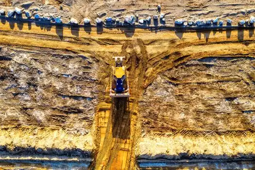
The dominant failure modes are outrigger punch-through (more relevant to mobile cranes but instructive as a worst case), uneven settlement, and tip events, all of which trace back to demand exceeding capacity at one support [S1]. For crawlers, the equivalent failures are track pad sinkage on soft clay, pad cutting into loose sand, and differential settlement that takes the crane out of level mid-lift. Damaged track pads, uneven crane mats, and poor subgrade compaction all amplify these failure modes [S3].
OSHA 1926.1402 is the binding US federal requirement, setting that the ground must be firm, drained, and graded to meet manufacturer support and level specifications, and placing the responsibility on the controlling entity [S1]. Australian and New Zealand guidance (CICA / CANZ) reinforces the principle that ground integrity is a primary stability factor. The pressure sensor on a hydraulic load-moment indicator reads hook load, not ground pressure, which is why the calculation is still done by hand or with a dedicated calculator rather than read off the LMI in the cab.
Trackable signals for the next planning cycle: manufacturer-published track-pad width options and their effect on ground pressure (Liebherr, Manitowoc, Tadano, Sany all publish per-configuration pressure charts), updated CICA / CANZ guidance on combined-loading peak factors, and any 2026 revision to OSHA 1926.1402 subparagraph (b) on ground conditions. Until those land, the inverse-proportional rule between pad width and ground pressure, and the 100 / 200 kN/m² action thresholds, remain the working numbers on every lift plan.