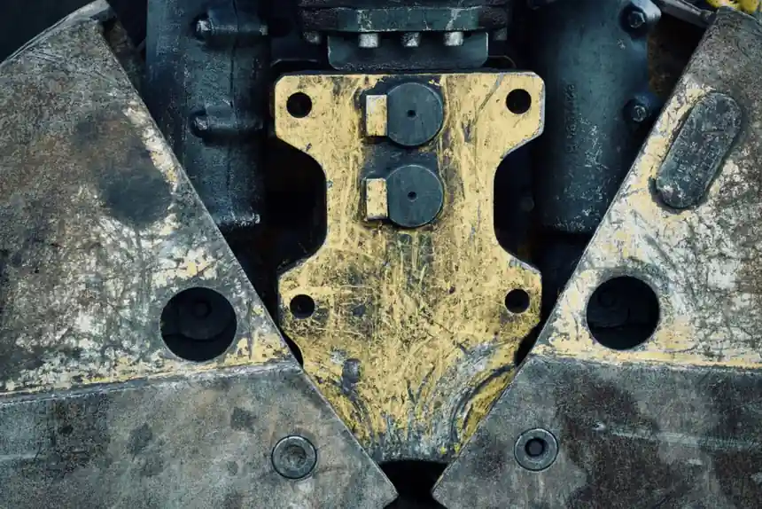
Cement plants punish linear motion hardware with abrasive dust, temperature swings above 50 °C around kilns, and vibration peaks above 10 g at roller presses, so the crossed roller guide is a credible candidate for short-stroke, high-load axes like clinker cooler pushers, damper actuators, and sampling car traverses.
Crossed roller guides are precision rail guides with flat cages, typically specified for stroke lengths under 1 m [S1]. Compared with linear guide products that use recirculating balls, they offer higher load capacity, higher rigidity, and almost stick-slip-free motion, with the trade-off that travel is limited because the cage does not recirculate [S1][S2].
Why Cement Duty Tilts the Decision Toward Crossed Rollers
Crossed roller guides transmit load through line contact of cylindrical rollers, so their static load capacity and tilting moment stiffness exceed equivalent-size ball-rail designs of the same cross-section [S1]. That matters on a roller press slide gate or a preheater damper, where the load is rarely pure radial: moment from a misaligned actuator, side load from a sticking damper blade, and shock from process upsets all show up at the same time.
Crossed roller guides also avoid the pulsation that recirculating-ball roller bearing systems induce as balls enter and exit the load zone, which is why precision machine builders like Sodick have used them for long machine life on short-stroke axes [S3]. In a cement environment, low pulsation translates into less mechanical noise transmitted into structural steel and less fatigue cycling on the bolted interface.
Spec Gates That Decide Acceptance or Rejection
Stroke length is the first gate. Crossed roller guides are designed for limited stroke lengths, typically less than 1 m [S1]. If the required travel exceeds roughly 0.8 to 1.0 m, a recirculating linear roller rail becomes the lower-risk choice, because the non-recirculating cage cannot be extended without leaving unguided rollers in the load path.
Static load and tilting moment rating are the second gate. Schaeffler's crossed roller bearing SX series corresponds to ISO dimension series 18 with a very small section height, and can support axial forces in both directions, radial loads, tilting moments, and any combination of loads [S4]. For cement service, the static limiting load should be checked against peak process loads, not just nominal operating load, because clinker cooler pusher forces can spike during a sticky bed.
Mounting surface quality is the third gate. Crossed-roller slides are factory-preloaded to eliminate clearance and minimize deflection under load, but the manufacturer achieves the rated accuracy only when the installer mounts them to a suitably rigid and flat surface [S2]. In a cement plant, that usually means a machined carbon-steel sub-plate with a flatness under 0.05 mm/m and a bolt pattern sized to keep joint stiffness high.
Materials, Sealing, and Anti-Creep for Dusty Service

Abrasive cement dust is the single biggest environmental threat to a crossed roller guide. Del-Tron supplies its aluminum and steel crossed roller tables with stainless-steel rails and roller cages for corrosion resistance, and offers an Anti-Creep design that prevents roller cage migration under vertical orientation, high acceleration, or shock load [S5]. In a clinker cooler area, both features are worth specifying together, because vertical or angled damper actuators see high deceleration loads at end of stroke.
Sealing must be addressed in the adjacent construction. Schaeffler notes that crossed roller bearings must be provided with seals in the adjacent construction, and that the design of the adjacent construction has a considerable influence on the function of the bearings [S4]. For cement duty, that means double-lip nitrile or felt wipers on the carriage, plus a positive-pressure air purge if the guide sits inside an enclosure where dust load is constant.
Surface finish and roller geometry should be checked. Precision ground V-grooved ways and rollers, with alternately crossed rollers at 45°, let the table withstand force in any direction, a useful property when the load vector rotates as a cooler pusher cycles [S5].
Comparison Against Alternative Linear Motion Options
The realistic alternatives for cement-plant short-stroke axes are recirculating-ball linear guides, recirculating-roller linear guides, and plain crossed-roller ways. Compared on four decision criteria, the picture sharpens. A recirculating-ball linear guide handles the longest strokes, but offers the lowest load capacity and the highest pulsation. A recirculating-roller linear guide handles long strokes with high load and low pulsation, but costs more and is larger. A plain crossed-roller way carries the highest load per unit cross-section with the smoothest motion, but is restricted to strokes under about 1 m [S1][S2][S3].
For damper and gate duty in a cement plant, where stroke is short and load is heavy, crossed-roller ways win on three of the four criteria. For longer-travel functions such as a sampling car running the full kiln length, the recirculating-roller rail is the correct match. Specifying the wrong type is the most common failure mode and shows up as either premature cage wear on an over-stroked crossed-roller way, or structural deflection on an under-rated ball-rail slide gate.
Installation and Maintenance Constraints Specific to Cement Plants
Crossed roller bearings require a minimum load to prevent damage due to slippage during slow or oscillating motion, and the bearing arrangement must be designed so that this minimum is always exceeded under the worst process condition [S4]. For a damper that holds position for hours, the actuator's own weight and any bias spring must be confirmed to exceed the minimum load requirement at every angle.
Lubrication strategy should be locked at the selection step. Both grease and oil lubrication are possible, and grease lubrication is generally the lower-maintenance option for cement plant locations where access is restricted and dust contamination is high [S4]. A grease specification compatible with ambient temperatures up to 80 °C, with a relube interval aligned to plant shutdown windows, is the practical baseline.
Mounting screws need their own design check. The dynamic and static load carrying capacity of the fixing screws must be verified against the bearing's load, including the worst-case tilting moment, because screw failure is a common root cause in field returns on crossed-roller slides [S4]. Use a torque-controlled tightening method and a thread-locking strategy rated for the vibration environment.
Who Should Specify Crossed Roller Guides, and Who Should Not
Crossed roller guides are a good match for plant engineers responsible for short-stroke, high-load, high-precision axes in dusty environments, including damper actuators on preheater towers, clinker cooler pusher carriages, and laboratory or quality-control stages inside cement mills. They are a poor match for long-travel functions, ultra-high-speed axes, or applications where a single catastrophic dust ingress event cannot be excluded by sealing design. [S3]
Procurement teams that value interchangeability should also check that the selected crossed-roller table is dimensionally interchangeable with the incumbent supplier's product line, since Del-Tron explicitly markets its slides as interchangeable with other manufacturers' slides [S5]. That single decision can cut retrofit downtime from days to hours during a kiln outage.
Trackable Signals to Confirm Over the Next Maintenance Cycle
Three signals are worth watching after installation. First, measured cage migration at the end of each scheduled inspection, because any non-zero value on a non-anti-creep design indicates a load or alignment problem before wear becomes visible. Second, peak static load per cycle logged from the actuator load cell, because trending this value against the crossed-roller guide's static limiting load gives a clean remaining-life indicator. Third, relube interval closure against the original schedule: grease that comes out black with cement fines confirms seal failure and triggers a sealing redesign before the bearing surface is damaged. Specifying the bearing is only the first step; verifying these three signals over the first 12 months is what separates a clean retrofit from a repeat failure. [S4]
Background reading: GWR Level Meter Selection for HVAC Loops: Spec Gates and Vendor Map.