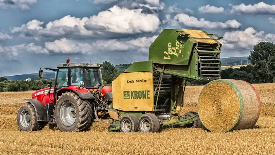
Agriculture machinery is one of the harsher non-marine environments a ball spline will see, and the spec logic for it diverges from clean factory floors. Field equipment runs in dust, mud, fertilizer mist, and seasonal temperature swings, often with shock loads from rocks, root balls, and stalled rotors. The four spec gates that decide selection are shaft diameter, accuracy class, torque type, and sealing.
Commercial spline shafts in agriculture builds typically land in the 15–40 mm diameter band, with H (high) and P (precision) accuracy grades specified wherever a servo or stepper drives the axis and sub-25 µm repeatability is required. Medium-torque LT and LF series cover the bulk of linear-rotary applications, while high-torque LBS, LBST, and LBF units are reserved for spindle drives under continuous shock loading [S2][S4].
Where the Ball Spline Actually Lands on a Tractor or Combine
Ball splines on agriculture equipment are not generic linear guides; they show up on axes that must rotate and stroke at the same time, which is a narrower set than a general purpose linear guide handles. Documented field applications include steering column height-and-tilt mechanisms, sprayer boom fold and yaw axes, planter row-unit downforce actuators with rotational indexing, combine header tilt and reel adjustment, baler plunger guides on rotary wrappers, and tiller or rotary cutter spindle supports [S1][S2].
What makes the ball spline the right call over a plain linear bushing is the torque transmission: a plain bushing cannot resist rotation, so the axis would need a separate pin or key. The ball spline's rolling-element contact keeps friction in the 0.001–0.005 range and lets the nut travel and lock to a rotor on the same shaft, which is why it shows up on automatic loader arms, transfer machines, and tire molding machines in the THK application list, and the same logic carries to header reels and boom yaw drives in agriculture [S1][S2].
Shaft Diameter and Construction: 15–40 mm Is the Working Band
Shaft diameter is the single most consequential dimension because dynamic load rating scales with the square of the ball-circle diameter, and stroke length is bounded by shaft length. Catalog spline shafts span 6–50 mm overall, but the agriculture working band is 15–40 mm: 15–20 mm for row-unit downforce and small boom fold axes, 25–32 mm for header tilt and reel lift, and 40 mm for baler wrapper spindles and large planter toolbar shift drives [S5].
Solid shafts are the default because through-shaft cabling and weight reduction rarely matter on a tractor the way they do on a SCARA arm. Hollow shafts get specified when the shaft doubles as a hydraulic or electrical pass-through, for example in a header reel that needs both rotary power and a center hydraulic feed. For long horizontal strokes above roughly 1 m, hollow sections also reduce sag deflection and the positional error it adds, which matters for planter toolbar shift where end-of-row accuracy stacks up across many cycles [S5].
Accuracy Classes N, H, and P Under Field Conditions
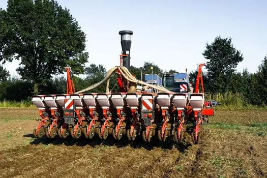
Three accuracy grades appear on standard splines: N (normal), H (high), and P (precision), with each step roughly halving the running-parallelism error between the spline nut and the shaft reference datum. In agriculture builds the split is not even. Grade N suits non-servo transfer functions like manual fold booms or mechanical spring-loaded row units, where 10–25 µm repeatability is not on the spec sheet. Grade H covers most electrohydraulic and servo-driven axes, header tilt, and GPS-guided boom height control, where the operator or controller can resolve a few tens of microns. Grade P is reserved for seed-metering servos and planter singulators where sub-5 µm bi-directional repeatability is required to hold population targets [S5].
Preload and clearance class are usually specified alongside accuracy because the field environment punishes backlash. Heavy preload raises drag torque and heat generation, which is the right trade on a combine header running all day, but wrong on a fold boom that is stroked once per pass. The published JIS B 1192 ball-screw framework that THK extends to its splines defines the parallelism bands and preload classes, and agriculture buyers typically lock in Z0 or Z1 preload on H grade for the most common header and boom applications [S1][S5].
Torque Type and Series Selection: LT/LF vs LBS/LBF
THK's published selection logic splits ball splines into three functional groups: high-torque type, medium-torque type, and rotary type. High-torque models LBS, LBST, LBF, LBR, and LBH use three crests at 120° with two rows of balls per crest, six rows total, and a 45° contact angle that gives high rigidity and large torque capacity in 15–150 mm diameters. Medium-torque models LT, LF, LT-X, LF-X, LFK-X, and LFH-X use two or three crests with a 20° contact angle, suiting lighter moment loads in the 4–100 mm range, and the X variants share outer dimensions with LM-series linear bushings so the nut can be swapped for a plain bushing if torque is dropped later [S2][S4].
For agriculture, the medium-torque LT and LF series cover the majority of axis applications, and the choice between them is mostly a contact-angle and rigidity question. A row-unit downforce actuator with a small rotation stop only needs LT with its 20° contact. A header tilt actuator that fights wind gusts and ground contour on every pass needs the LT class at the upper end of its diameter range, or moves up to the LBS high-torque class. A baler plunger drive or rotary cutter spindle that sees continuous shock loading with peaks above 200 N·m is the case for LBS or LBF, with shaft diameter at 32–40 mm [S2][S4].
Sealing, Lubrication, and the Dust Problem
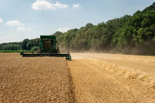
Dust and fertilizer residue are the dominant failure drivers in agriculture, not load. Standard catalog seals keep grease in and gross contamination out for factory duty, but field duty needs upgraded sealing: double-lip nitrile wipers, felt excluders, or stainless bellows on the exposed stroke. Most OEMs ship the spline nut pre-greased with a calcium-sulfonate or lithium-complex grease rated for −20 to 120 °C, but the maintenance interval in field conditions is half the factory interval, typically 500 hours or seasonally, whichever comes first [S1][S4].
Where the environment is dry and clean, standard through-hardened or case-hardened bearing steel at 58–62 HRC is fine. In acidic fertilizer mist or manure-handling equipment, the raceway zones need a corrosion-resistant surface treatment, and stainless or chrome-plated shafts are common in sprayer applications. Hardness below 58 HRC reduces rolling-contact fatigue life, which is what the L10 calculation in the next section is built on [S1][S5].
Load Life, the L10 Calculation, and Shock Derating
Dynamic load rating C and static load rating C0 are the two published numbers that drive sizing, with the L10 life given by L = (C/P)^3 × 50 km for ball-bearing-style contact mechanics, where P is the equivalent applied load. Stroke frequency, moment loading from cantilevered attachments, and contamination from the surrounding process environment all feed into the equivalent load term [S5].
Agriculture duty rarely sees steady load, so the standard ISO 281 shock-factor approach is mandatory: typical field shock factors of 1.2–1.8 are applied to P before the L10 cube is taken. For a header tilt axis that cycles once per pass at 6 km/h with a 1.2 m stroke, the equivalent load is dominated by wind and ground-contour moment, and the L10 result must still clear a 5,000–8,000 hour design life, which is the typical warranty horizon for the machine. Static load rating C0 catches the worst-case stall condition, a rock jam on a row unit or a plugged cutter, and most agriculture spec sheets demand C0 with a 1.5× safety factor against the stall peak [S1][S5].
Comparison Table: Series Selection by Field Application
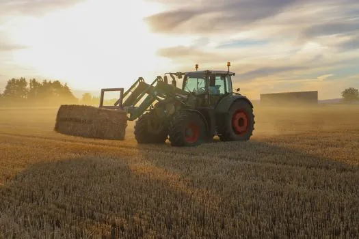
The four spec criteria below are the ones a buyer should pin down before the catalog opens. Series choices are read against typical field applications to make the trade-off visible at a glance. [S5]
Pairing with Bearings, Linear Guides, and the Servo Loop
Ball splines on agriculture equipment are almost never stand-alone; they share the axis with a ball screw on the same shaft for some functions, or a separate ball bearing for radial support on others. When the spline is paired with a ball screw on a common axis, the two elements' thermal growth coefficients must be matched or the assembly will bind at temperature. When the spline carries a cantilevered rotor, a separate ball bearing or construction machinery and equipment support bearing takes the radial load and the spline carries torque and axial load only [S1][S3].
On a planter row-unit downforce actuator, the typical stack is a brushless servo, a ball screw for linear travel, a ball spline for the rotational indexing of the seed disc, and a ball bearing at the rotor end. This is the pattern that makes the agronomy precision work, and the spec gates that hold the stack together are the same ones that govern a SCARA Z-theta column in a clean room, just with harder sealing and a thicker wipe of grease [S1][S3]. For applications that sit even closer to metalworking duty, the die-casting selection logic for die casting die selection for agriculture machinery shares the same shock-factor and 5,000–8,000 hour design-life posture that drives spline sizing.
The two trackable signals to watch in the next spec cycle are THK's published updates to the SLS caged-ball spline line, which has reached 25–60 mm diameter coverage and lists agriculture-relevant applications like transfer machines and automatic loaders, and the gradual migration from N to H grade as more electrohydraulic and servo functions replace manual fold and mechanical spring functions on mid-range tractors. Buyers sourcing splines for 2027 model-year equipment should pin the catalog revision date on the spec sheet and confirm the caged-ball option is offered in the diameter band required before locking the print.