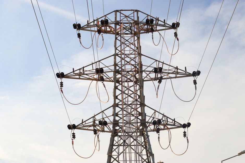
A current transformer (CT) is defined as an instrument transformer in which the secondary current is proportional to the primary current and ideally carries zero phase difference, with accuracy class quantifying how closely the secondary mirrors the primary [S6]. CTs are the workhorse for metering and protective relaying on medium- and high-voltage circuits, stepping bus currents of hundreds or thousands of amps down to 1 A or 5 A secondary [S2].
Selection is rarely about the core alone: primary current, ratio, burden in VA, accuracy class, rated frequency, and physical format (bar-primary, wound, window, clamp-on) all interact, and misjudging one will saturate the core or skew revenue-meter readings [S5]. The guide below distils 2026-published reference material into a practical spec map covering definition, criteria, type comparison, use cases, and limits.
Definition, Working Principle, and Why a CT Is Not a Power Transformer
A CT operates on the same electromagnetic principle as a power transformer, with primary and secondary windings on a laminated silicon-steel core, but the operating point is fundamentally different [S3][S6]. The primary is often a single turn (the bus bar or a cable pass) carrying the full line current, while the secondary has many turns and is closed through a low-burden instrument or relay [S3].
Because the secondary drives a near-short-circuit (burden in VA is small compared to a power transformer's kVA load), the core flux density stays low and the secondary current is set almost entirely by the primary ampere-turns divided by the secondary turns [S6]. An open-circuited secondary, however, removes the counter-magnetising MMF and lets flux ramp to saturation, inducing dangerous over-voltages across the secondary terminals — which is why CT secondaries must always be shorted or landed on a burden before energising the primary [S2][S6].
For related substation hardware such as the upstream MV/LV transformer feeding the bus being metered, see the dry-type transformer selection reference or the power-transformer fundamentals page.
Selection Criteria: Ratio, Burden, Accuracy Class, Rated Frequency
Rated primary current must cover the maximum load with margin; a common rule is to size primary current at roughly 1.0–1.25× the maximum sustained load current so the CT does not approach saturation during normal operation [S5]. Standard secondary is 5 A (with 1 A variants for long runs to limit lead burden), and standard ratios span 50/5, 100/5, 200/5, 400/5, 800/5, 1200/5 and beyond [S1][S5].
Burden is the total impedance, in VA, presented to the secondary: meter coil, relay coil, leads, and joints [S2]. A CT rated 15 VA will saturate early if the actual loop measures 30 VA; conversely, a CT sized to a much larger burden than necessary has wasted margin. At 1 A secondary, voltage drop in long leads shrinks, which is why 1 A secondaries are preferred when the meter sits tens of metres from the CT [S2].
Accuracy class follows IEC 61869-2 conventions: metering classes such as 0.2, 0.2S, 0.5, 0.5S, 1, 3 give ratio-error limits at defined burdens, with 0.2S/0.5S covering extended current range down to 1% of rated [S5]. Protection classes (5P, 10P, PR, PX) specify composite error at a defined accuracy-limit primary current, typically 5–20× rated [S5]. Frequency is usually 50 Hz or 60 Hz; a CT designed for 50 Hz can be installed on a 60 Hz network at the same accuracy, but the reverse is not true and must be stated on the order [S5].
Type Comparison: Bar-Primary, Wound, Window, Clamp-On
Construction decides cost, retrofit-ability, and the maximum primary current the CT can carry without saturating. Four formats dominate the market, and the choice is largely driven by whether the bus is already in service [S1][S3].
Yokogawa's CTW clamp-on line, for example, ships in 100 A, 200 A, 500 A and 800 A standard ratings plus compact 100 A and 300 A bodies, the whole point being no conductor cutting and lower install cost on retrofits [S1]. Where CTs must feed revenue-class meters, prefer a solid-core window or bar-primary with 0.2S or 0.5S class instead, because split-core geometry adds ratio and phase error [S5][S1].
Use Cases: Metering vs Protection, Indoor vs Outdoor
Metering CTs feed revenue meters, power-quality analysers, and SCADA; they are optimised for accuracy near rated current and 0.2–0.5 class is standard on HV billing points [S5][S6]. Protection CTs feed overcurrent, differential, and distance relays, and are optimised to remain linear up to 20× rated primary during a fault, accepting 5–10% ratio error at normal load in exchange [S5].
Indoor MV switchgear typically uses cast-resin bar-primary CTs in the 11–36 kV class; outdoor HV installations use oil-immersed or SF6-insulated units with porcelain or composite bushings, sized for both short-time thermal current (Ith, typically 25–40 kA for 1 s or 3 s) and dynamic peak current (Idyn ≈ 2.5 × Ith) [S5]. For energy monitoring on existing low-voltage feeders — data centres, building management, sub-metering — clamp-on CTs avoid outage and the need to re-terminate the conductor, which is why they are the default for retrofits [S1].
Limitations, Failure Modes, and Sourcing Standards
The dominant failure modes are core saturation (CT gives up ratio accuracy and clips at high primary), open-secondary over-voltage (potentially lethal at the terminals), and burden overshoot (loop impedance higher than rated) [S2][S5]. Temperature drift, external electromagnetic fields, and physical CT orientation (especially of wound types) are secondary but real accuracy shapers [S2].
Applicable international standards are IEC 61869-1 / IEC 61869-2 for instrument transformers in general and CTs in particular, plus IEEE C57.13 in North American practice; for utility revenue metering the regional metering code will pin accuracy class and test points [S5]. Where CTs are used in hazardous-area switchgear, enclosure certification (ATEX 2014/34/EU or IECEx) is specified at the assembly level, not on the CT alone [S5]. Buyers should also confirm short-time thermal current, dynamic current, and continuous thermal rating factor (e.g. 1.2× or 1.5× at the reference ambient) match the site's prospective fault level and ambient temperature [S5].
Who Should NOT Pick the Mainstream Option, and Why
Clamp-on CTs are the go-to for retrofit energy monitoring, but they should not be used for revenue-grade billing on the utility side of the meter because the air gap and split-core construction push ratio error above the 1–2% envelope that billing codes require [S1][S5]. Equally, a metering-class CT (0.2S) wired into a differential protection scheme will saturate under an external fault and let the relay misoperate; protection CTs (5P, 10P, PX) are deliberately less accurate at rated current in exchange for linearity at 10–20× rated [S5][S6].
A wound-primary CT specified for 5 A primary is also the wrong pick on a 600 A feeder; the secondary will be forced to carry 600 A equivalent into the burden and saturate or burn. Match the primary rating to the bus, the accuracy class to the application, and the format to the installation constraint [S3][S5]. Buyers who need both metering and protection on the same bus should provision separate cores in the same CT body, or stack two CTs with appropriately assigned duties, rather than over-task a single core.
For adjacent substation components that share the same kVA, insulation, and short-circuit considerations as the CT, see the oil-immersed transformer price reference and the dry-type transformer spec map; for the linear-motion hardware used in tap-changer drives, the linear-guide fundamentals and crossed-roller guide pages are useful supporting reads.
The trackable signal for the next 1–2 quarters is whether IEC 61869-2 amendment material on low-power CT outputs (mA-class, for process-bus metering) shows up in vendor datasheets at 100–800 A primary, since that would shift the clamp-on vs solid-core trade-off in metering cabinets. A second signal is the publishing cadence of utility metering-code updates adopting 0.2S at 1% of rated, which would tighten the billable-accuracy floor across the European MV billing segment [S5][S6].