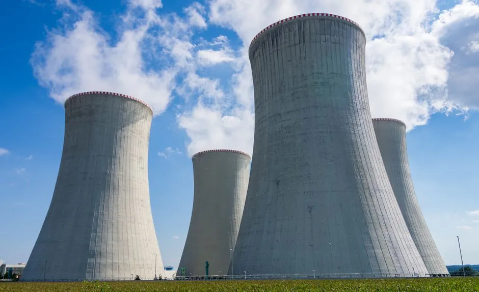
Selecting a cycloidal reducer for cement plant service means matching shock-load capacity, ambient dust, and ambient temperature to auxiliary drives, not the kiln shell, where hardened helical units remain the workhorse [S3][S2].
Cement plants are heavy-industry sites in the strict sense: continuous duty (often 24/7, 300+ days per year), ambient temperature up to 45 °C in the mill building, abrasive limestone and clinker dust above 10 g/m³ near crushers, and shock loads from jaw and impact crushers, bucket elevators, and pan mixers [S2][S1]. A practical cycloidal reducer selection therefore has to answer four questions up front: where in the cement process, what ratio and torque envelope, what ambient condition, and what standard governs the rebuild and the gear material.
Where a Cycloidal Reducer Fits in a Cement Plant, and Where It Does Not
A cycloidal reducer carries load through a cycloidal disc engaging a ring of stationary pins, with typically 40 to 60 percent of the pins in simultaneous rolling contact, which is why it is rated for shock loads 2 to 3 times higher than a comparable cylindrical unit of the same frame size [S3]. In a cement works that mechanical advantage is wasted on the rotary kiln main drive, where kiln output speed sits at 0.4 to 4.0 r/min, motor power runs 200 to 1,200 kW+, and the service factor Ka = 2.0 is the spec; here hardened helical reducers in the ZDY/ZLY/ZSY families stay standard [S2].
For auxiliary cement applications, cycloidal units earn their place: pan and planetary concrete mixers, slurry agitators, bucket elevator heads, screw conveyors feeding the raw mill, and clinker cooler discharge drives. A cement plant gearbox audit should split drives into two lists: main drive (kiln shell, raw mill, cement mill, roller press) and auxiliary drive (agitator, elevator, conveyor, cooler), and only run the cycloidal shortlist across the auxiliary list.
Spec Ranges That Matter: Ratio, Torque, Service Factor
Cycloidal reducers ship in single-stage ratios typically 6:1 to 87:1, and two-stage builds extending that envelope to about 121:1 to 15,000:1, with output torque frames from 100 N·m up to 50,000 N·m per stage depending on housing size [S3]. A cement bucket elevator head typically wants 20:1 to 60:1, while a pan mixer or slurry agitator more often sits in 30:1 to 120:1. Single-stage efficiency is around 90 to 95 percent, dropping into the 85 to 90 percent band on two-stage units because the second cycloidal stage adds internal loss [S3].
The service factor is the number that gets misapplied. For a pan mixer that starts under a full load of damp raw meal, Ka = 1.5 to 1.75 is a defensible baseline; for a jaw crusher or impactor in the limestone quarry feeding the plant, push to Ka = 2.0 to 2.5 with a starting factor check, because the first-tooth contact event during crusher no-load-to-load transition can hit 250 percent of nominal [S1]. Pair that with daily operating hours: above 16 h/day continuous, multiply the catalogue rating by an additional 1.1 to 1.25 derate per AGMA-style service-factor tables (this is a generic heavy-industry convention, not a cycloidal-specific standard).
Side-by-Side: Cycloidal vs Hardened Helical for Cement Service

On four decision criteria, the comparison is sharp. Shock load capacity: cycloidal wins, with multiple rolling contact points versus 1 to 2 engaged teeth on a helical pair [S3]. Efficiency: hardened helical wins, with single-stage efficiency ≥96.5 percent versus about 90 to 95 percent for a single-stage cycloidal [S2][S3]. Continuous-duty thermal stability: hardened helical wins, with case-hardened gears at HRC 58 to 62 and forced-circulation lubrication, a configuration cycloidal housings do not match at the same output torque [S2]. Footprint and weight per kW: cycloidal wins, typically 30 to 50 percent lighter and shorter than a helical unit of equivalent rated torque thanks to the disc-and-pin geometry [S3].
That is the trade-off matrix to write into a gear reducer selection memo: cycloidal where shock and compactness dominate, hardened helical where efficiency and thermal headroom dominate. A separate row goes to the harmonic reducer family, which is generally not used in cement at all outside laboratory-scale material testing, because its torque density and backlash class suit robotics rather than 24/7 mill-house duty.
Materials, Sealing, and Lubrication for the Mill Environment
Cement mill ambient dust is alkaline (CaO and Ca(OH)₂ fines), and ambient temperatures of 40 to 55 °C near cooler and preheater are normal, so the cycloidal housing needs a minimum of IP55 enclosure protection, oil seals rated for 80 °C continuous, and a breather with a dust filter rather than a simple vent plug [S1][S3]. For the cycloidal disc itself, through-hardened bearing steel (typical 20CrMnTi case-carburised to HRC 58 to 62, or 40Cr quenched and tempered) is the cement-industry default; the pin ring is almost always GCr15 bearing steel, hardened to HRC 60 to 64 [S1].
On lubrication, splash lubrication is acceptable for vertical-shaft cycloidal units under 5 kW input; for anything driving a pan mixer or bucket elevator above 7.5 kW, forced-circulation with an oil cooler and 25 µm in-line filtration is the conservative choice, mirroring the recommendation in the ZY-series hardened helical retrofit guide [S2]. Oil change interval in a dusty cement site should be halved versus the manufacturer's clean-environment figure, so 2,000 to 3,000 hours rather than 5,000 hours, and the breather inspected monthly. A cement and concrete process engineer running this checklist at handover will catch most early-life failures before the kiln is turned over for production.
Failure Modes Engineers See in the Field
The four failure modes that show up repeatedly in cement-plant cycloidal service: pin-ring spalling from abrasive ingress when the breather filter is missing or saturated; cycloidal disc-tooth wear at the high-speed stage when the oil cooler has failed and sump oil runs above 90 °C; output-shaft seal leakage when the seal lip is the wrong compound for the alkaline dust (NBR fails, FKM or PTFE-lip seals survive); and bearing failure on the eccentric bearing when the start-stop frequency exceeds the rated cycle count [S3].
The hardened helical main drive on the kiln has a different failure distribution: pitting, scoring, and tooth breakage from surface fatigue on through-hardened gears after 15 to 25 years, which is the specific case driving the ZY-series retrofit conversation in the cement sector right now [S2]. On a retrofit, do not assume a cycloidal drop-in is feasible, because the ratio envelope, foot-mount dimensions, and input coupling alignment on kiln main drives are typically helical-specific. For a special cement and high-wear service line such as a calcium sulfoaluminate or oil-well grade, the same dust and temperature regime applies, only the maintenance budget tends to be tighter, which pushes the choice back to a cycloidal auxiliary drive with a smaller spare-parts inventory on site.
Standards, Sourcing, and Practical Sizing Steps
For sourcing, the cement industry typically writes gear reducers to GB/T 10095.1-2008 (accuracy of involute cylindrical gears) for helical units, to GB/T 15183-1994 or equivalent ISO 6336 for gear strength calculation, and to AGMA 2001 or ISO 1328 for noise and accuracy class; cycloidal units in Chinese supply are typically built per JB/T 9050.1 or factory standards referencing the same ISO 6336 load-capacity methodology [S1]. Require a documented gear-cutting certificate and a no-load, partial-load, and full-load acceptance test report at the OEM floor before shipment, because a gear reducer quality checklist caught at the supplier is cheaper than a teardown in a kiln outage window.
Track these signals: kiln main-drive retrofits to ZDY/ZLY/ZSY hardened helical units through 2026-2027, as the existing 20- to 30-year-old fleet reaches the end of second overhaul [S2]; and wider availability of two-stage cycloidal units with IP66 sealing and integrated oil coolers, which is the build that now matches cement ambient conditions rather than food-grade stainless specifications [S3]. For the auxiliary drives, those two trends are the ones to bake into the next cycloidal reducer selection for cement plants specification revision.
This topic is covered further in Smoke Detector Selection for Warehouses: 2026 Spec Map.