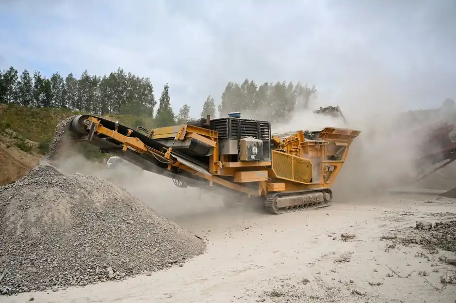
A cycloidal reducer converts a high-speed motor input into low-speed, high-torque output through an eccentric cam acting on cycloidal discs that engage a stationary ring of hardened pins, with multiple pins sharing the load at any instant, which is why mining engineers keep specifying them for crushers, conveyors, hoists, and agitators with high inertial mass and repeated shock loading [S2][S3].
For heavy-industry duties, that mechanism delivers torque density high enough to shrink the gearbox envelope, and shock-load capacity that the same engineering references call out as a defining advantage over conventional helical gearing on cyclic-load equipment [S3][S2].
Why Cycloidal Beats Helical, Planetary, and Worm on Mining Shock Loads
Multiple rolling contact points engage simultaneously inside a cycloidal disc, so transmission load is distributed across many pins rather than the one or two teeth that carry the load in a conventional involute mesh, which is the mechanical reason a cycloidal reducer survives the impact profile of a jaw crusher or a tripped conveyor better than a standard helical unit [S2][S3].
For comparison, a planetary reducer is the typical alternative for compact, high-ratio, high-precision servo and slewing duties, but the same physics mean fewer contact points carrying higher unit stress during cyclic peaks, which is why most mining specifiers still reach for cycloidal first and treat planetary as a precision-motion option, not a heavy-shock one.
Selection Inputs That Decide the Service Factor
The eight data points that drive the correct service factor for a mining cycloidal are motor power and rated speed, required output speed and torque, daily operating hours, load type and shock-load classification, start-stop frequency, shaft radial load, ambient temperature, and installation position, and skipping any one of them is the documented root cause of units that fail 18 months in [S1][S3].
The selection logic from the cylindrical-gear reference, which applies identically to cycloidal sizing, states that a reducer matched to motor power will frequently be undersized for equipment with high inertial mass, peak loads, reverse running, and long operating hours, so the engineer must compare required output torque against the actual load on the driven machine, then layer a service factor on top that reflects starts per hour and shock profile, not steady-state nameplate [S1]. Mining drives in particular run 16 to 24 hours per day, see ambient dust that contaminates oil and accelerates bearing wear, and frequently include reverse running for clearing stalled conveyors, all of which push the effective service factor above 1.5 even on a unit that looks lightly loaded on the nameplate [S1][S3].
Stage Count, Ratio, and Torque Map for Mining Duty
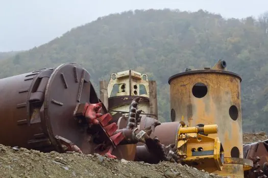
Single-stage units cover moderate speed reduction for simple layouts, two-stage covers the bulk of conveying and lifting duties with a wider ratio range and stronger torque, three-stage handles crushers, heavy conveyors, and cement equipment where lower output speed and higher torque dominate, and four-stage is reserved for slow-speed, high-torque systems where a large reduction ratio is mandatory [S1].
For a typical 1,500 rpm 4-pole motor driving a 30 to 60 rpm crusher or apron feeder, the math is a 25:1 to 50:1 ratio, which is exactly the window where two-stage and three-stage cycloidal units sit, and the same window where the multi-pin contact advantage shows up most because the pin-and-disc engagement remains fully populated across the full reduction [S1][S2]. A three-stage helical stack would also reach this ratio but at a longer axial envelope, more weight on the input shaft bearings, and a single-tooth-load pattern that the same references identify as the limiting factor on shock-loaded mining service [S3].
Components, Materials, and Environmental Hardening
A standard cycloidal unit consists of an input shaft, eccentric bearing or cam, one or two cycloidal discs, a stationary ring of output pins or rollers, an output shaft, and a housing, and the components that fail first in mining service are almost always the seals and bearings, not the discs themselves, because dust ingress and oil contamination get past a marginal seal long before the disc geometry gives up [S2][S1].
Heavy-industry specifiers reference high-strength alloy steel gears with carburizing, quenching, and precision grinding for tooth-surface durability and fatigue resistance on the gear pair, and the same hardening logic applies to the cycloidal disc lobes and the pin-gear ring where those components carry the contact stress, with the housing designed for rigidity and the seal package designed to keep ISO VG 220 or 320 mineral oil inside while excluding airborne dust common to crusher booths and transfer points [S1][S3]. For ultra-high-ratio or zero-backlash precision duties, a harmonic reducer is the more common reference, but harmonic units are not the workhorse choice for mining shock because the flexspline fatigue envelope is the limiting factor, not a contact-strength problem. For high-ratio, compact, right-angle duties on screens and agitators, an RV reducer overlaps with cycloidal and is sometimes the correct answer, but the RV variant is more sensitive to overhung load and radial shaft load than a parallel-shaft cycloidal, which is a real constraint on belt-conveyor head-pulley retrofits.
When a Cycloidal Reducer Is the Wrong Choice

Cycloidal units are not the right call for fractional-horsepower precision servo axes, where harmonic and planetary dominate the selection, and they are also the wrong call for very long continuous-duty high-horsepower main drives on grinding mills, where multi-megawatt helical or planetary gearsets with controlled lube systems are the standard reference [S3].
The same sources flag three concrete failure modes: undersized service factor with no allowance for shock, marginal seal selection that lets abrasive dust into the bearing cavity, and lubricant grade mismatched to ambient temperature, all of which are specification errors rather than gearbox-design errors [S1][S3]. A common engineering mistake is sizing for motor nameplate horsepower rather than the worst-case peak that a blocked crusher or a stalled inclined conveyor will impose, which is the scenario that scores the gear teeth and spalls the bearings in the first 18 months of service [S3].
Comparison: Cycloidal vs Helical vs Planetary vs Worm on Mining Criteria
On four decision criteria drawn from the same references, cycloidal scores 85 to 95% efficiency, high shock-load capacity, high torque density, and moderate backlash; helical scores 96 to 99% efficiency per stage, moderate shock capacity, moderate torque density, and low backlash; planetary scores comparable efficiency to helical with high torque density and high precision, but lower shock tolerance than cycloidal on a like-for-like frame; worm scores 50 to 90% efficiency depending on ratio, low shock capacity, and high ratio in a single stage, which makes it the cost-down choice for low-duty, low-cycle, non-mining service [S3].
The 50 to 90% worm range is the operative figure when a specifier considers a worm unit for a low-speed conveyor: the lead angle and ratio drag efficiency to the bottom of the band, and the heat rejection requirement scales with the lost power, which is exactly the wrong trade for an underground coal conveyor with limited ventilation [S3]. The 96 to 99% helical figure, by contrast, is the reason helical survives on steady-duty pumps and fans in mineral processing, where there is no shock spike to expose the single-tooth load path [S3].
Standards, Sourcing, and What to Verify on the Datasheet
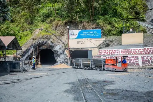
For mining-class gear units, the engineering references emphasize documenting the specification basis, including motor power, ratio, output speed, service factor, mounting configuration, environmental rating, lubrication match to ambient, alignment provisions, and maintenance accessibility, with the explicit warning that a gearbox without an installation record is a gearbox that will be misdiagnosed at first failure [S3].
Specifiers should also confirm on the datasheet the actual service factor for the unit's AGMA or equivalent classification, the ambient temperature rating versus the mine's measured ambient (which is routinely above 40 deg C near transfer houses), the seal package rating against IP55 or IP65 dust-ingress requirements, and the lubrication interval versus the expected dust load, since the same references state that gearboxes which cannot be inspected or sampled do not get inspected or sampled, and the rebuild cost on a failed cycloidal in a remote pit is multiples of the upfront price difference [S1][S3]. The selection guidance also recommends planning maintenance access at the specification stage, not after the gearbox is welded into the head-pulley structure, because retrofitting access on a live conveyor is the single most common reason a marginal unit is run to failure rather than serviced on schedule [S3].
Trackable next nodes for specifiers in this category: confirm the duty-cycle service factor against the mine's actual starts-per-hour log, and verify the lubricant grade against the measured ambient at the gearbox mounting, because both are the documented leading indicators of premature failure on cycloidal units in crusher and conveyor service.
See also our earlier report, Carbon Fiber Selection for Electronics: 2026 Spec Map.