A shop-grade dial indicator in the 0.001" (0.01 mm) graduation class with a 1.0" (25.4 mm) full stroke is the safe default for milling, turning, and fixture-gage work, and the 0.0005" class is reserved for dial test indicators used on alignment passes [S1][S4].
Buyers also need to decide plunger versus lever contact, ANSI/AGD group 1 or group 2 size, and whether a digital readout earns its keep in the environment; each of those three choices changes price and usability more than the brand name on the bezel [S1][S3][S5].
Plunger Dial Indicators vs Lever Test Indicators
A plunger dial indicator (DI) measures linear displacement along the spindle axis, making it the right tool for fixture gaging, depth comparison, and any application where a known zero is set against a reference standard [S1][S5]. A dial test indicator (DTI) reads the small angular deflection of a lever-style contact, so it is mechanically the better choice for indicating spindle runout, tram alignment, and surface comparison on a mill table [S1][S6].
DTIs are also physically smaller and lighter than DIs, which is why experienced machinists keep both on the bench: a DTI sneaks into the jaw of a vise to tram a vise to the table ways, while a DI is mounted in a Noga-type holder for tramming a head or measuring spindle-to-table parallelism over a 6" travel [S1][S4]. The two types are not interchangeable; selecting the wrong contact type is the single most common mistake first-time buyers make on a Practical Machinist thread that has run since 2010 [S4].
A lever contact also tolerates slight surface irregularities better than a flat plunger tip because the contact point pivots on its own arc, which is why DTI bodies are commonly combined with V-blocks or centers for roundness and runout on cylindrical parts [S1].
Graduation, Range, and Dial Reading Logic
A 0.001" / 0.01 mm indicator is the consensus general-shop device, while 0.0001" (2.5 µm) graduations are too fine for ordinary machining and tend to read noise rather than signal [S4].
A common 0.001" group 2 DI specification reads one full pointer revolution at 0.10" (2.54 mm) and carries a total travel of 1.0" (25.4 mm), so a machinist must track the small-pointer revolution counter plus the outer dial to recover absolute position across the full stroke [S1]. A metric 0.01 mm group 2 indicator from the same product class typically offers a 10 mm total range per revolution 1.0 mm, so the same logic applies in metric [S1].
For DTI work on a mill, the 0.0005" (0.0125 mm) graduation is the practical sweet spot: one forum respondent reports a DTI at 0.0005" is enough to confirm alignment within 0.001" across 6" of table travel, which is the working tolerance most home-shop and light-production mill alignments actually demand [S4].
Mechanical vs Digital Readout
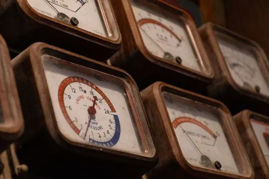
Mechanical dial indicators are the better fit for rough, demanding, coolant-soaked environments and for buyers who prefer a tactile, glanceable reading, and they cost less than their digital counterparts at the same accuracy class [S3].
Digital indicators (often styled digital dial indicators or DTI-plus-readout) are worth the premium only when the workflow needs preset values, inch/millimeter switching, data output to a SPC system, or operator-level zeroing without a bezel clamp, because the analog bezel-zeroing step is exactly what digital units automate [S3][S5]. They are also the only sensible choice when the operator cannot view the dial face along its normal plane, since the LCD can be tilted and is backlit; analog units are constrained by the geometry of where the eye can be placed relative to the pointer [S5].
Failure modes differ as well: a mechanical DI can be dunked in coolant, knocked, or run past its mechanical stop with limited consequence, while a digital unit's encoder and battery compartment add two more things that can fail in a shop environment, so most general shop users still anchor their work on a mechanical indicator and only add a digital unit where the application demands it [S3].
Specifications That Drive the Decision
The five specifications that actually drive a purchase decision are: graduation (resolution), total range, repeatability, bezel rotation / clamp type, and stem / lug-back geometry, and each one rules out a meaningful slice of the market [S1][S5].
A typical 0.001" group 2 specification is: 0.001" graduation, 0.10" per revolution, 1.0" total range, 2-1/4" (57 mm) dial face, stainless-steel racks and bottom bearings, hardened steel spindle, 90-degree rotatable lug back, and a 3/8" (8 mm) mounting stem; that combination is the de-facto reference spec for a US-shop group 2 indicator [S1]. A metric 0.01 mm / 10 mm group 2 indicator with a 8 mm stem, stainless-steel body, hard-coated crystal, and improved dust and water sealing is the equivalent reference spec in metric shops [S1].
A buyer who skips any one of those five criteria ends up re-buying within a year, which is why experienced machinists pay a premium for sealed crystals, stainless internals, and a bezel that locks positively rather than with friction [S1][S5]. Industrial buyers who already use pressure transmitters and flow meters on a process skid will recognize the same pattern: sealing, stem geometry, and a positive clamp matter more than the brand decal.
Comparison Table: 0.0001" vs 0.0005" vs 0.001" Indicators

The class comparison below maps graduation, typical use, total range, and who should not buy it, so a buyer can shortlist without measuring anything; numbers reflect what the source articles report for each class [S1][S4].
0.0001" / 0.0025 mm graduations: best for laboratory and gage-room metrology; total range typically around 0.04-0.05" (1-1.3 mm); not appropriate for routine mill/turn work because pointer motion between marks is hard to read at production tolerances [S4]. 0.0005" / 0.0125 mm graduations: best for DTI alignment passes and surface comparison; total range on a DTI is typically 0.030" (0.8 mm); not appropriate as the only shop indicator because the small range limits how far a part can drift before the indicator runs out of travel [S4]. 0.001" / 0.01 mm graduations: best general-shop device; full 1.0" or 25-30 mm total range; not appropriate when the application needs sub-micron resolution or when shop air or vibration is severe enough to mask a 0.0001" reading [S1][S4].
Brands frequently named as the safe defaults in the source material are Mitutoyo, Starrett, Brown & Sharpe, Tesa, and Interapid/Compac/Intrepid on the DTI side, with second-hand purchases explicitly flagged as risky because calibration state is unknown [S1][S4].
Setup Hardware and Where the Reading Fails
Almost every bad reading on a dial indicator traces back to the base and arm, not the indicator itself, and a magnetic base is the single most-cited setup accessory across all sources [S1][S2].
Standard procedure: place the magnetic base on a clean, ferromagnetic reference surface (a diff housing is the textbook example for ring-and-pinion backlash work, but a mill table or column is just as common); position the arm so the contact tip meets the workpiece at 90 degrees to the surface being measured; and tighten the arm so there is no preload or flex, because any play in the arm is a direct error in the readout [S2]. For a DTI, the tip should be aligned along the axis of plunger travel on the part, with the indicator body close enough that the lever contact stays within its specified arc, usually within about 20 degrees of its centerline [S2][S6].
The bezel should be zeroed at the start of each measurement by loosening the bezel clamp, rotating the bezel to zero with the plunger preloaded, and re-clamping; a friction-only bezel will drift during the job and is a common source of repeatability complaints on cheaper units [S2].
Who Should Pick Which Variant

Pick a 0.001" / 0.01 mm plunger DI for general shop use: mill alignment, lathe alignment, fixture gaging, depth comparison, and spindle runout via a part reference, and budget for a Noga-style holder or a magnetic base with fine adjustment at the same time [S1][S4]. Pick a 0.0005" DTI for tram work, surface comparison, and any job where the indicator must reach into a narrow gap that a plunger cannot enter [S1][S4]. Pick a digital indicator only if the operator needs unit switching, data output, or a readout visible from awkward angles; otherwise a mechanical unit is more durable for the same money [S3][S5].
Skip the 0.0001" DI for production machining because the dial face is too small to interpolate reliably at production tolerances, and the indicator will read vibration as motion; reserve that class for gage-room work and calibration [S4]. Skip a digital indicator if the work area is wet, oily, or exposed to flying chips, unless the unit carries an explicit IP rating and impact-tested bezel [S3].
Trackable Next Signals
Two signals are worth watching over the next buying cycle: whether Chinese ISO 9001 / ANSI/AGD-spec DIs continue to close the gap with Mitutoyo and Starrett on repeatability at the 0.001" class, which would reset the price benchmark; and whether more digital indicators begin shipping with native Bluetooth or USB output to SPC packages, which would shift the cost calculus toward digital at the 0.0005" / 0.01 mm class [S3][S5].
For a complementary view on stainless-steel hand tools and the stainless-steel pricing signals that affect indicator bodies and contacts, and on caliper and micrometer sourcing where graduation classes overlap with indicator selection, the field map articles in this issue cover the broader precision-tool landscape.
For component-level specifications, see dial indicator.