
The TAMAYA TD-4 provides an RS-232C output for transferring digital azimuth and elevation measurements to a computer, while its built-in memory can retain as many as 100,000 records [S1].
Its data path supports balloon tracking and upper-air wind analysis, with a smallest displayed angle of 0.01° for both horizontal and vertical readings [S1]. Unlike a general-purpose data logger, the TD-4 is a digital balloon theodolite designed around angle measurement, instrument storage, RS-232C transfer, and optional real-time printing [S1].
Digital Theodolite Data Architecture
A digital theodolite measures horizontal and vertical angles with electronic encoders, microprocessors, and an LCD rather than requiring an operator to read a vernier or micrometer scale [S2]. That distinction determines how the instrument can feed a data logger: the measurement system produces digital angle values, and the logging workflow must preserve the record structure, timestamps, instrument settings, and transfer sequence [S2].
The TD-4 displays azimuth and elevation with a smallest display unit of 0.01°, and its azimuth display covers 0–360° [S1].
The TD-4 is intended for tracing a pilot balloon and using azimuth and elevation data to describe upper-atmospheric conditions [S1]. Its transfer method is therefore not simply an office export. The same observation sequence can feed immediate computer analysis, internal review, printed records, or later processing into altitude versus wind direction, altitude versus wind speed, and pilot-balloon path graphs [S1].
RS-232C Output to a Computer or Logger
The TD-4’s external input/output function is RS-232C, and the manufacturer identifies a PC connection cable and dedicated data-processing software as supporting items [S1]. A logger connected through this interface should therefore be tested as an RS-232C endpoint with compatible cable wiring, baud rate, parity, data bits, stop bits, and handshaking before field deployment, rather than assuming that a general-purpose USB or network logger can connect directly.
The instrument can also operate without a separate collector because it stores measurements internally, up to 100,000 data items [S1]. This creates two practical acquisition modes: direct output while the instrument is in use, and batch retrieval from built-in memory. The second mode is useful when a field location has poor connectivity, when observations must be preserved before a computer is available, or when the operator prefers to review stored records on the TD-4 display [S1].
With the optional printer, the TD-4 can print data in real time [S1]. Printing does not replace digital logging, but it provides a separate observable record for checksums, spot verification, and field review. A logger commissioning test should include one printed page and one transferred file so that both paths can be reconciled against the instrument display.
Instrument Selection Criteria
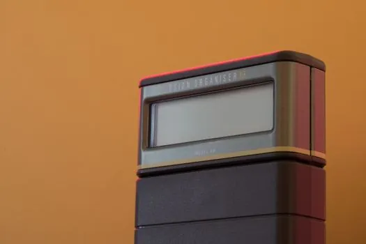
The TD-4’s main telescope has a 47 mm objective, 18× magnification, a 2°30′ field of view, and 3.5″ optical resolution; its sub-telescope has a 16 mm objective, 4× magnification, an 11° field of view, and 12″ resolution [S1]. These optical values matter for target acquisition, while the 0.01° digital resolution, RS-232C interface, and 100,000-record internal memory determine the practical logging envelope [S1].
The TD-4 weighs 5.2 kg [S1].
A logging plan based on long unattended recording must check battery charge, storage capacity, sample frequency, and the time needed for post-session export. The Topcon DT-207 is associated with 7-second accuracy [S3].
Internal Storage Compared with Live Transfer
Internal storage offers a higher capacity ceiling in the TD-4 specification, with up to 100,000 measurement data items retained on the instrument [S1]. Direct RS-232C output offers an earlier path for analysis because a computer can receive measurements while collection continues. The choice is therefore not simply storage versus no storage, since the same instrument can use both capabilities.
The internal route is better suited to protected batch operation, while the serial route is better suited to live computation of the pilot-balloon path or wind relationships.
For a conventional construction survey, a digital theodolite may be selected primarily for fast electronic angle display and reduced reading error, but the TD-4 is a specialized meteorological instrument rather than a general construction-layout solution [S1][S2]. Its balloon-tracking purpose, RS-232C interface, built-in memory, and upper-air analysis software form a coherent acquisition chain that a logger must support [S1].
Field Commissioning and Failure Checks
Commissioning should begin with instrument leveling, because the listed 90″/2 mm tubular-vial sensitivity provides the reference for correcting tilt before observing targets [S1]. The operator then checks azimuth and elevation against the display, confirms the 0–360° presentation for both axes, and compares a live RS-232C record with the instrument’s internal measurement history [S1].
Records should be named against a documented observation sequence rather than transferred as an undifferentiated file. Each exported set needs at least the observation identifier, azimuth, elevation, and observation time, with the real-time clock checked before collection [S1]. Sample interval must also be recorded because the balloon-path and wind graphs are generated from azimuth and elevation observations captured at specified intervals [S1].
Four failure modes deserve explicit checks: a mismatched RS-232C serial setting, a reversed or incomplete cable connection, a full internal-memory condition, and loss of power during transfer. The 100,000-record limit and approximately 20-hour operating time provide the two hard capacity checks, while the display and optional printer provide independent ways to verify that useful data was captured [S1].
Applicable Measurement and Recording Scope
The recording chain is defensible when every exported angle can be tied to a measured azimuth and elevation, a defined observation interval, and a valid instrument setup. The TD-4’s supported outputs are concrete: 0.01° smallest display units, 0–360° azimuth and elevation ranges, up to 100,000 stored measurements, RS-232C external communication, and Excel-format storage through the supplied processing software [S1].
This arrangement is not a substitute for specifying a logger protocol beyond what the instrument supports. The evidence identifies RS-232C, but it does not establish a universal command set for arbitrary loggers, a USB converter requirement, or a named industrial protocol such as Modbus [S1]. Any logger purchase should therefore begin with a documented RS-232C interface test using the manufacturer-supported cable and software environment, followed by verification of file structure, timestamps, and record counts [S1].
A useful tracker for procurement is the combination of sample rate, expected session duration, and expected observation count. For example, a logger set to capture one record every 10 seconds would generate 360 records per hour, but the comparison must be made against the actual transfer schedule and the TD-4’s internal capacity rather than inferred from nominal sample-rate claims [S1]. The decisive acceptance criterion is a round-trip record count with matching azimuth and elevation values on the instrument, exported file, and logger.