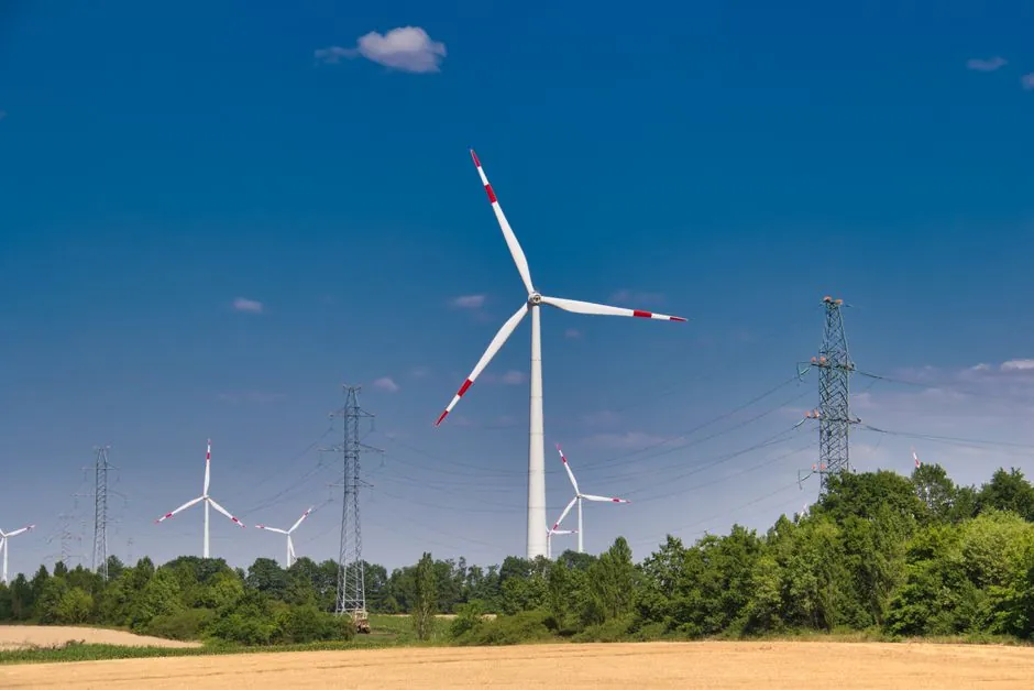
Zero-Max's flexible composite disc couplings are rated for a 20-year operating life and tested across -57 to 121 C with C4 high corrosion resistance, with field deployments spanning Vestas V47, Siemens-Gamesa G5X/G8X/G9X/G114, Nordex AW-1500, and Unison U88/U93/U113 turbines [S1].
Continuous torque demand on multi-megawatt wind drivetrains routinely exceeds 3 million in-lbs (roughly 339 kNm), the figure Gearbox Express specified for its down-tower test stand coupling in 2021 [S5].
Core architecture: composite disc pack, floating shaft, or close-coupled
Disc couplings transmit torque through a stack of thin stainless steel discs, typically 0.4 to 1.0 mm each, 4 to 12 deep, bolted alternately to driver and driven hubs at opposite bolt circles, with the disc pack flexing elastically to absorb angular and axial misalignment without sliding parts, lubrication, or backlash [S4].
Wind applications branch into three physical layouts. Floating-shaft designs use two single-flex couplings plus a center spacer machined from steel, composite glass fiber, or 6061-T6 aluminum, with the spacer engineered by FEA for torques above 70,000 Nm depending on material [S2]. Close-coupled variants, including the Lovejoy SXC and SXCS families, mount hubs inside or adjacent to the spacer for compact gearbox-to-generator spacing, with SXCS split-spacer designs letting disc packs be removed without disturbing the hubs [S3]. For a general primer on how flexible shaft couplings sit inside a rotating drivetrain, the disc coupling reference covers the geometry and flex-element behaviour.
Torque, speed, and misalignment sizing rules
Lovejoy disc packs accept 0.5 to 1.5 degrees of angular misalignment per flex plane depending on model, and the same supplier publishes an API-610 balance and piloting compliance path up to 3,800 RPM with ATEX certification across the SU, SX, DI, SXC, SXCS, SXCST, DIR, DILR, DIRA, and DIRLA lines [S3].
Sizing logic for wind service starts with the peak torque envelope across the 20-year load spectrum, then derates for temperature, misalignment-induced fatigue, and any torsionally resonant drivetrain modes. The Firgelli interactive calculator frames it as utilization = |theta| / theta_allow, with margin and safety factor tracked per flex plane, a useful sanity check for OEM-published limits [S4]. For wind service, the open-arm composite geometry is specifically chosen because it carries large parallel and angular offset while keeping reaction forces on the generator bearings low, the reason Zero-Max's wind couplings survived Tehachapi wind farm testing in 80+ mph winds with continuous direction changes [S1][S2].
Electrical isolation and bearing protection

Composite flex elements electrically insulate the generator from the gearbox, eliminating amperage leakage across the coupling and protecting gearbox bearings and teeth from EDM pitting, a failure mode that has taken more than 50 non-isolated couplings out of service at the Tehachapi test site [S1][S2].
This isolation is one of the structural reasons dielectric composite disc packs displaced metallic disc packs on most modern turbine drivetrains. The same composite material family also handles moisture, chemicals, and the 178 C swing between -57 and 121 C without derating, a range that covers North Sea offshore cold-soak to desert midday hub temperatures [S1]. The disc pack itself is typically AISI-301 stainless, chosen for high fatigue endurance and environmental resistance in Lovejoy's product line [S3].
Comparing the three main disc-coupling architectures against decision criteria
Floating-shaft, close-coupled, and drop-in spacer designs differ on the criteria that drive wind-turbine specification: torque capacity per envelope, service access, balance class, and ATEX coverage. The table below lines them up against the four most common selection filters. [S3]
Floating-shaft composite disc couplings (e.g. Zero-Max wind series) deliver the highest continuous torque per outer diameter, support large parallel offset from the gearbox-generator stand-off distance, and use a dielectric flex element for bearing-current isolation; their trade-off is larger envelope and the need to align a long center spacer at install. Close-coupled SXC/SXCS variants keep envelope short for integrated nacelle layouts and let the disc pack be serviced through split spacer hardware without moving hubs, but torque density per OD drops and the spacer must be custom-matched to the shaft separation [S3][S8]. Drop-in spacer (DI) couplings add piloted hubs to meet API-610 anti-flail and balance requirements, a useful fit on liquid-hydrocarbon or process-side machines that share API-610 balance discipline with wind test stands [S3].
Corrosion, certification, and 20-year service life

Offshore and high-humidity onshore sites are pushing couplings to C4 high corrosion resistance as a baseline, with Zero-Max stating all components meet or exceed C4 and are manufactured to ISO 9001:2015 quality standards [S1]. The same supplier publishes a 20-year-plus operating life target, longer than the typical driveline coupling, and lists ATEX and IECEx-class certification routes for hazardous-area nacelle installations through the Lovejoy product family that carries ATEX on the SU, SX, DI, SXC, SXCS, SXCST, DIR, DILR, DIRA, and DIRLA lines [S1][S3].
Geislinger's GESILCO DISC is a competing architecture aimed specifically at closed-coupled generator sets and highly integrated wind powertrains, optimized for short shaft separations where a floating-shaft spacer would not fit [S8]. PSC's Series 57-4628 illustrates the upper end of the torque envelope, hitting 3.125 million in-lbs continuous for a 1 MW down-tower test stand, with flanges that release the gearbox and motor while leaving the center member assembly in place for quick changeover [S5].
When a disc coupling is and is not the right answer
For turbines above 1.5 MW, for any drivetrain with documented bearing-current damage, or for nacelle layouts that need 20-year maintenance-free service, composite disc couplings with dielectric flex elements are the default choice, supported by field data from Tehachapi and OEM cross-reference tables covering Acciona, Vestas, Siemens-Gamesa, NEG Micon, and Unison platforms [S1][S2].
Where the application is low-torque (under roughly 1,000 Nm continuous), highly contaminable with abrasive dust, or where misalignment is dominated by large parallel offset that the disc pack cannot absorb, a jaw or gear coupling is usually a better fit; jaw couplings tolerate more parallel offset, gear couplings handle higher torque density, and disc couplings remain the only one of the three that combines torsional rigidity, zero backlash, and electrical isolation in a single lubrication-free package [S3][S9]. For applications where a coupling is paired with a brake, clutch, or torque limiter in the same drivetrain, the Zero-Max torque-limiter add-on integrates with the same composite disc coupling footprint to give overload protection on top of the flex element [S1].
Sourcing, standards, and what to verify before order

Specifying engineers should confirm four data points before release: continuous and peak torque across the published load spectrum, angular and parallel misalignment envelope per flex plane, electrical isolation voltage rating of the flex element, and corrosion class plus temperature range against the installed site [S1][S3][S7].
Trackable signals over the next planning window include ATEX/IECEx certification status for the specific part number (not just the product family), API-610 balance and anti-flail compliance for test-stand builds, ISO 9001:2015 manufacturing certification, and a documented 20-year FEA-validated fatigue life [S1][S3]. For a process-engineering view of how this drivetrain component interacts with the wider rotating-equipment package, the power distribution and power supply references cover the upstream electrical side that the dielectric flex element is protecting.
Related analysis: Truck and Port Crane Selection for Terminal Operations: 2026 Spec Map.