
Modern dynamic balancing instruments commonly resolve residual unbalance to 0.4 g·mm/kg, equivalent to 0.4 μm of equivalent radial displacement, on precision bench machines such as the VTM 9D718 [S4]. Portable field units typically cover 1–50 g·mm across two correction planes, with resolution scaled to rotor mass and service speed.
The unit g·mm is the vector product of residual mass and its radius from the rotation axis, the same quantity that produces the rotating centrifugal force at a given RPM. A rotor spinning at 3,000 RPM with only 10 g of unbalance at 150 mm radius generates roughly 150 N of rotating force, enough to destroy bearings in weeks if left uncorrected [S1].
How g·mm Resolution Maps to ISO 21940-11 Balance Grades
The applicable balance grade is set by ISO 21940-11 (formerly ISO 1940), which expresses permissible residual unbalance as G·mm/kg, where G is the grade number scaled to service speed [S1]. Common industrial grades span G 6.3 for machine-tool drives and electric-motor armatures up to G 0.4 for precision grinder spindles and dental drill turbines, with the same units directly comparable to instrument resolution [S1][S3].
For a 10 kg rotor running at 3,000 RPM, a G 6.3 grade permits roughly 630 g·mm of specific unbalance, while G 2.5 tightens the budget to 250 g·mm and G 1.0 to 100 g·mm. A bench balancer with 0.4 g·mm/kg sensitivity [S4] has the headroom to verify grades tighter than G 1.0, whereas a portable field unit with 5 g·mm absolute resolution is appropriate only for verifying G 6.3 and coarser on similar masses.
Single-Plane vs Two-Plane Instrument Architecture
Single-plane (static) balancers correct mass offset in one disc-shaped correction plane, and they apply only to rotors where the diameter is more than 7× the width: flywheels, grinding wheels, brake discs, saw blades, and single-disc impellers [S1]. They sense only the centrifugal force component and do not detect couple unbalance, where two equal masses sit 180° apart in different planes with zero net force but a real torque.
Two-plane (dynamic) balancers use two accelerometers near the bearings plus a photoelectric trigger to extract magnitude and phase in each correction plane, then compute the influence-coefficient matrix to recommend trial-weight mass and angle [S6][S7]. This architecture is mandatory for elongated rotors (shafts, fans, mulcher rotors, multi-stage pump impellers, turbines) and is the only configuration that catches the dynamic unbalance case where the principal inertia axis neither intersects nor parallels the rotation axis [S1][S3].
What Drives the Resolution Spec Sheet

Instrument resolution is governed by four factors: minimum measurable specific unbalance (g·mm/kg or μm), the rotor mass range, the maximum achievable trial weight, and the speed range of the drive (belt-, air-, or end-drive) [S5]. High-end bench machines hit 0.4 g·mm/kg = 0.4 μm with permanent calibration and operator-controlled setup to maximize sensitivity on small armatures [S4].
Field-grade portable instruments trade absolute resolution for adaptability: they handle rotors from a few grams (dental spindles) to 200 kg (mulcher rotors) [S1] and rely on the trial-weight influence-coefficient method to back-calculate mass and angle at each plane [S7]. Resolution below 1 g·mm absolute is rarely meaningful in the field because run-to-run speed variation and environmental vibration dominate the noise floor; the bench environment is what unlocks sub-μm measurements.
Selection Criteria: Who Needs Sub-g·mm and Who Does Not
Sub-g·mm resolution is mandatory for gas turbine compressor rotors, machine-tool spindles, G 0.4–G 1.0 grade armatures, and any rotor where unbalance above 1 g·mm drives 1×-RPM vibration above 4.5 mm/s RMS at the bearings. For a broader view of mass range and pedestal selection on shop-floor machines, see the rotor range 1 kg to 50 t selection guide. [S5]
Portable 1–50 g·mm instruments are sufficient for ISO G 6.3 and coarser work: HVAC fans, pump impellers under 50 kg, motor armatures in the field, and crusher rotors. Two-plane measurement is essential whenever the rotor length exceeds roughly half its diameter, regardless of resolution, because static-only balancing leaves the couple component uncorrected [S1][S3]. The instrument must also accept a once-per-revolution reference (photoelectric or magnetic pickup) to lock phase; without it, the magnitude reading is valid but the angular position is arbitrary [S6][S7].
Comparison: Bench vs Portable vs Spinning-Field Instruments
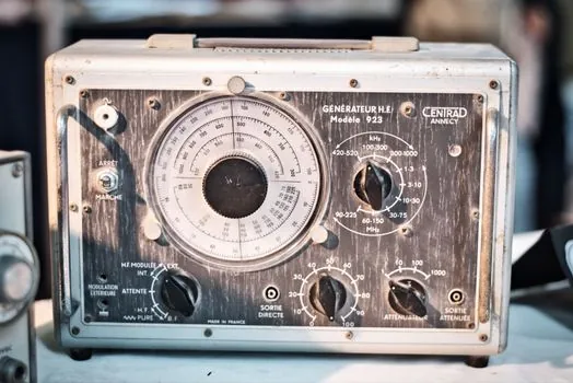
Three instrument classes compete for the same work, and the trade-off is sensitivity versus deployability. Bench-type soft-bearing machines deliver the best resolution (0.4 g·mm/kg) and permanent calibration, but require the rotor to be removed from service and transported to a controlled environment [S4][S5]. Portable piezoelectric-based units offer 1–50 g·mm absolute resolution in a rugged case, sacrificing the last decade of sensitivity for on-site deployment in 30–45 minutes per rotor [S1][S7].
Spinning-field (in-place) balancers attach accelerometers directly to the bearing housings of the installed machine, compute influence coefficients from a known trial mass, and derive the two-plane correction without ever stopping the process, ideal for large turbo-machinery where removal is impractical. Across all three, the figure of merit is the same (g·mm/kg or μm/kg), but the achievable floor differs by roughly two orders of magnitude between bench and field units.
Limitations and Failure Modes of the g·mm Reading
Resolution is not accuracy. A 0.4 g·mm/kg spec means the smallest detectable change in unbalance, not the calibration confidence in the absolute reading; drift in the charge amplifier, temperature-induced offset in the piezoelectric accelerometer, and soft-bearing stiffness variation can each add 10–20% error to the absolute g·mm value if the machine is not thermally stable [S5][S6].
Run-to-run variation also limits the smallest repeatable g·mm number. A rotor balanced to a reading of 0.6 g·mm/kg on the first run may show 1.2 g·mm/kg on the second without any physical change, because residual thermal bow, electronic noise, and pedestal-mode coupling dominate below roughly 1 g·mm/kg in real conditions [S5]. The instrument is also blind to the axial component of unbalance: a perfectly balanced rotor with a bowed shaft will still read near zero on a two-plane machine, and the vibration is then diagnosed as alignment or thermal bow rather than balance [S3].
Standards, Sensors, and Sourcing
All reputable dynamic balancing instruments comply with ISO 21940-11 for grade classification and use the trial-weight influence-coefficient method defined in ISO 21940-21 for two-plane correction [S1][S7]. The standard sensor stack is two accelerometers near the bearings plus a once-per-revolution photoelectric or magnetic pickup for phase reference; a high-frequency composite sensor monitoring blade tip clearance has been demonstrated in 2024 work to identify unbalance without the OPR sensor, with improved accuracy over the traditional method on a rotor test bench [S2].
Practical signal chains: charge or IEPE accelerometers in the 1–10 kHz bandwidth feed into a spectrum analyzer or a dedicated balancing instrument, which extracts the 1×-RPM component, normalizes by speed, and reports g·mm in each plane along with the recommended correction mass and angle [S6][S7]. For background on the broader dynamic balancing machine classification and pedestal types, and on how balancing fits with downstream analytical instrument chains for vibration monitoring, the linked encyclopedia pages provide the hardware-side context.
Track three signals when specifying the next instrument: a published minimum specific unbalance in g·mm/kg, not just g·mm absolute; explicit compliance with ISO 21940-11 grade testing; and confirmed support for two-plane influence-coefficient calibration with a removable trial mass. The 0.4 g·mm/kg floor on precision bench machines is the current benchmark [S4], and any portable claim of sub-1 g·mm/kg should come with a calibration certificate rather than a brochure figure.
The underlying component specifications are covered under balancing valve.