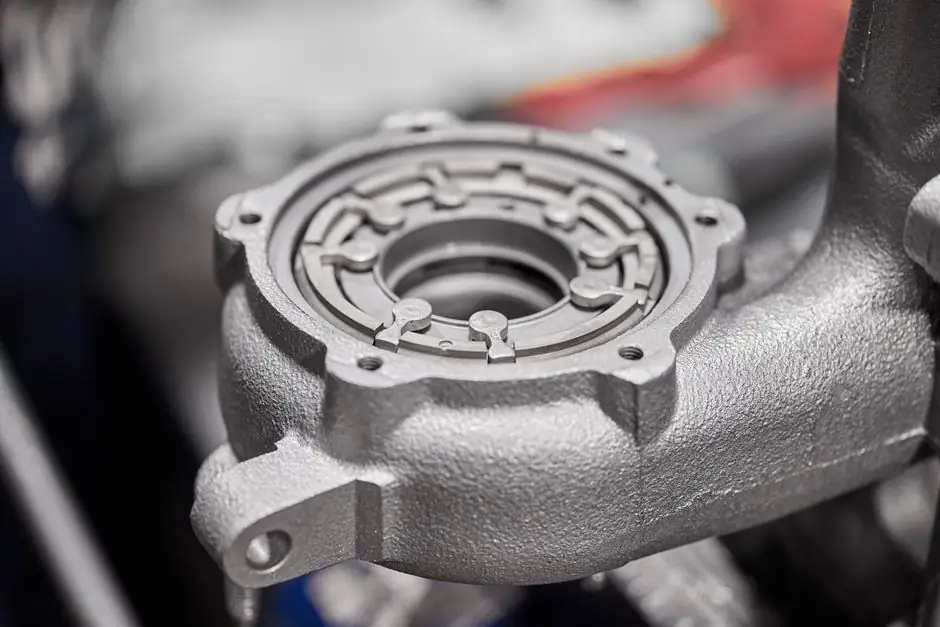
A dual-rotor turbine flowmeter places two counter-rotating rotors in series so the average rotor speed represents true volumetric flow regardless of upstream swirl, allowing turndowns of 120:1 to 500:1 in commercial designs versus roughly 10:1 to 100:1 for single-rotor units [S3][S4]. The hydraulic coupling of the two rotors cancels opposite-sign swirl effects, so most installations do not require upstream flow straighteners or extended straight-pipe runs [S2][S5].
This matters in compact skid builds, subsea pods, and engine test cells where pipework geometry is dictated by the equipment, not the instrument [S2]. For readers comparing flow technologies, the turbine flowmeter fundamentals entry covers the volumetric principle that both architectures share, and the counter-meter selection guide explains how dual-rotor pulse outputs feed batch and totalizer systems.
Principle of swirl cancellation in a dual-rotor design
The dual-rotor configuration uses two closely coupled rotors turning in opposite directions; fluid swirl that slows the front rotor speeds the rear rotor by a comparable percentage, so the sum or average of the two frequencies tracks the true flow rate even under distorted inlet profiles [S2]. This behavior is what lets the meter sit directly downstream of elbows, reducers, or headers without the 10D upstream straight-pipe run typically called out for single-rotor designs [S2][S5].
The same hydraulic coupling produces a secondary diagnostic channel: a flow processor monitoring the ratio of Rotor A frequency to Rotor B frequency can flag bearing wear or contamination as the two outputs diverge over time [S2]. Test campaigns with three out-of-plane 90-degree elbows, run with and without downstream flow straighteners, showed the dual-rotor meter held its accuracy profile in both configurations [S2][S8].
Turndown, accuracy, and pressure drop numbers from the field
Commercial dual-rotor turbine meters document repeatable flow ranges up to 500:1 and usable (UVC) turndown of 60:1 on the same line size; single-rotor turbine meters on equivalent sizes typically deliver 100:1 repeatable and 10:1 UVC turndown [S4]. The Cox Exact Dual Rotor datasheet lists linearity of ±0.1%, absolute accuracy of ±0.10%, pressure rating of 3000 psig, and NIST-traceable calibration uncertainties of ±0.05% with repeatability of ±0.02% at the Flow Dynamics NVLAP lab in Scottsdale, AZ [S3].
A 2024 CFD and calibration study on a dual-rotor flowmeter (DRT-FM) swept axial clearances from 0.50 mm to 0.80 mm across 200 to 1600 L/h; the 0.65 mm group delivered the lowest linearity error at 1.07% versus 3.33% in the 0.50 mm group, and the 0.80 mm group showed K-factor increases of about 6% relative to 0.50 mm [S1]. Pressure loss penalty was modest: at 1600 L/h the 0.65 mm configuration added only 0.186 kPa versus the 0.50 mm baseline, a useful ceiling when specifying pump head budgets [S1].
Selection criteria: where dual-rotor earns its premium
Dual-rotor architecture pays back in three conditions: line sizes under 2 in where single-rotor turndown is too narrow, installations with severe upstream distortion where straighteners are impractical, and applications needing bearing-health diagnostics over long service intervals [S6][S2]. For larger lines with calm, conditioned flow, a single-rotor turbine meter remains a cost-effective choice because its accuracy floor is not the limiting factor.
On material selection, the Badger Meter Cox Exact ships with 316 stainless steel housings, 17-4 stainless steel rotors, and ceramic ball bearings suitable for water and hydrocarbons, with 17-4 PH handling the high-shock loads seen in flight and hydraulic test stands [S3][S7]. Two housing variants cover the same internals: CDX in an explosion-proof body and CDL in a low-profile form factor for tight skid layouts [S3].
Installation, calibration, and limits engineers hit in practice
Install position does not affect the meter's performance, but calibration in the final installed orientation is recommended for precision applications; upstream filtration is advised to keep bearing contamination out of the rotor path [S3]. End fittings cover AN, NPT, flange, and hose-barb terminations, so the same meter can drop into aerospace, industrial, and automotive test rigs without adapter plates [S3].
Limits to track: rotor drag and torsional losses set the lower end of the flow range, and the wider the turndown the more sensitive the calibration to fluid viscosity and temperature; the dual-rotor addresses swirl but does not waive the standard turbine caveat that K-factor drifts with Reynolds number [S1][S2]. For process piping comparisons, the conductivity-meter page and the clamp-meter page cover the adjacent instrument categories a flow skid engineer typically pairs with a turbine meter in a maintenance toolbox.
Decision matrix: dual-rotor vs single-rotor on the four criteria that matter

Criterion 1, turndown: dual-rotor 120:1 to 500:1 repeatable versus single-rotor 10:1 to 100:1, so dual-rotor often replaces two single-rotor meters on a manifold [S3][S4]. Criterion 2, swirl tolerance: dual-rotor holds accuracy through three out-of-plane elbows with no flow straightener; single-rotor requires a flow straightener or 10D straight-pipe run in the same geometry [S2][S5][S8]. Criterion 3, installed footprint: dual-rotor eliminates the straight-run length and can remove the second meter and its manifold valves on a dual-range skid [S2]. Criterion 4, diagnostics: dual-rotor exposes a Rotor A/Rotor B frequency ratio that flags bearing wear; single-rotor offers no equivalent internal cross-check [S2].
Specifying a single-rotor design is the right call when the flow is conditioned, the line is 2 in or larger, and turndown below 100:1 is acceptable; the dual-rotor design is the right call when the upstream is dirty, the layout is short, and the operator wants a single instrument to cover what previously took two meters plus a manifold. The full single-girder crane and reactive-power-compensation pages sit outside this flow topic but are useful adjacent references on the broader process-instrument spec site.
Track two signals going forward: OEM publications of expanded size ranges for the CDX/CDL family, and any 2026 CFD or calibration work extending the 0.50-0.80 mm axial clearance data set into larger line sizes where the rotor-blade Reynolds number shifts. Related cross-reading for engineers sizing adjacent skids: the dual-input temperature transmitter SIL 2/3 piece and the roller vs ball bearing dynamic load rating comparison both cover redundancy and bearing-life decisions that intersect with dual-rotor bearing-diagnostic thinking.