A 6 m fill generally requires a medium-to-high dynamic-compaction energy class, with 10–20 t tampers dropped from about 15–25 m providing a practical initial range for granular fill.
The final program must reflect soil type, saturation, layer thickness, required density, and field response;
Initial energy range for 6 m of fill
For a 6 m target depth, begin with a tamper mass of 10–20 t and a drop height of 15–25 m, subject to confirmation by a site trial. Published equipment descriptions place heavy tampers in the 10–30 t class, while documented drop heights span roughly 9–24 m [S7]. Densification’s published operating range uses tampers weighing 6–30 t dropped from heights of 30–100 feet, but that full range is not automatically appropriate for a 6 m fill [S5].
Calculate nominal potential energy with E = W × h, using consistent units. A 15 t tamper dropped 20 m has a nominal potential energy of 300 kN·m before losses, while a 20 t tamper at 25 m has 500 kN·m. These values are useful for comparing proposals, but actual soil response depends on tamper geometry, contact area, impact sequence, soil state, and the number of drops [S4].
Dynamic compaction is generally better suited to granular fill with low saturation and good drainage. The method can improve loose sand, dredged or hydraulically placed fill, mine tailings, and heterogeneous fills containing debris [S3][S5]. It is not an appropriate default treatment for saturated clay, where rapid loading can generate adverse pore-pressure response [S3].
Energy options compared by duty
Low-energy treatment, represented by roughly 6–10 t tampers dropped 9–15 m, is more appropriate for shallow recompaction or relatively loose granular layers than for the full 6 m target. Medium energy, represented by 10–20 t tampers at 15–25 m, is the appropriate initial test range for a 6 m fill of clean sand or gravel [S5][S7]. High energy, above 20 t or above 25 m drop height, should be reserved for deeper treatment or soils that do not respond adequately at the initial energy.
The comparison uses published operating ranges, not a guaranteed depth-energy relationship [S4][S5][S7]. A 6 m deposit sits within the 3.0–10.7 m improvement range reported for suitable natural and fill deposits, but depth also depends on whether the objective is surface improvement throughout the fill or deeper densification below a defined interface [S1].
Fill profile and drainage determine feasibility
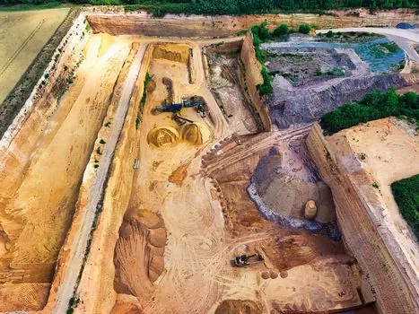
Log each fill horizon before selecting energy. Clean sand and gravel can transmit impact waves effectively, but fines, low permeability, high saturation, buried slabs, pipes, voids, and organic layers can interrupt or dissipate the energy [S3][S4]. A 6 m fill may behave differently across its full depth if it contains a dense crust, soft pocket, drainage barrier, or variable gradation.
Confirm the fill depth with the geotechnical model rather than relying on drawing grade alone.
For fills below the water table, granular soils can still be candidates, but pore-pressure generation and dissipation require control. Rest periods between phases may be needed, with pore pressure monitored using piezometers; saturated clay remains unsuitable for this method [S3].
Trial section before full production
Record crater depth, ground heave, rebound, elapsed time between passes, and settlement after each phase.
Use drop points on a grid so that the site receives a consistent nominal energy, then adjust spacing, passes, and drops from observed response. Published guidance identifies grid spacing, number of blows per point, drop height, and total passes as variables controlled by the energy required for site-specific conditions [S5].
Measure the result below the 6 m target, not only at the crater. Appropriate checks can include cone penetration testing, dynamic probing, nuclear density testing where appropriate, and settlement monitoring. The project acceptance criteria should define the required relative density, cone resistance, bearing capacity, or settlement performance; no universal density value can be derived from depth alone [S1][S2].
Ground response and failure indicators
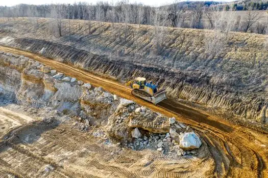
Excessive crater depth and persistent ground heave are direct signals to reduce or pause energy application. If heave develops, check whether the treatment is pushing the fill laterally or whether weak saturated material is trapping excess pore pressure rather than densifying [S3][S4].
Poor response can also indicate that the selected energy is not being transferred effectively. Dense layers, buried obstructions, plastic fill, or an unsuitable hammer setup can prevent the expected strain and settlement. The 2026 technical review identifies tamper mass, drop height, tamper geometry, impact spacing, number of blows, and initial soil properties as interacting controls on performance [S4].
Do not increase drop height mechanically when settlement is weak. First distinguish inadequate impact energy from excessive surface response, then verify saturation and pore-pressure conditions. Escalation should follow trial evidence, not an assumed linear relation between kN·m and treatment depth [S1][S4].
Crane and tamper selection constraints
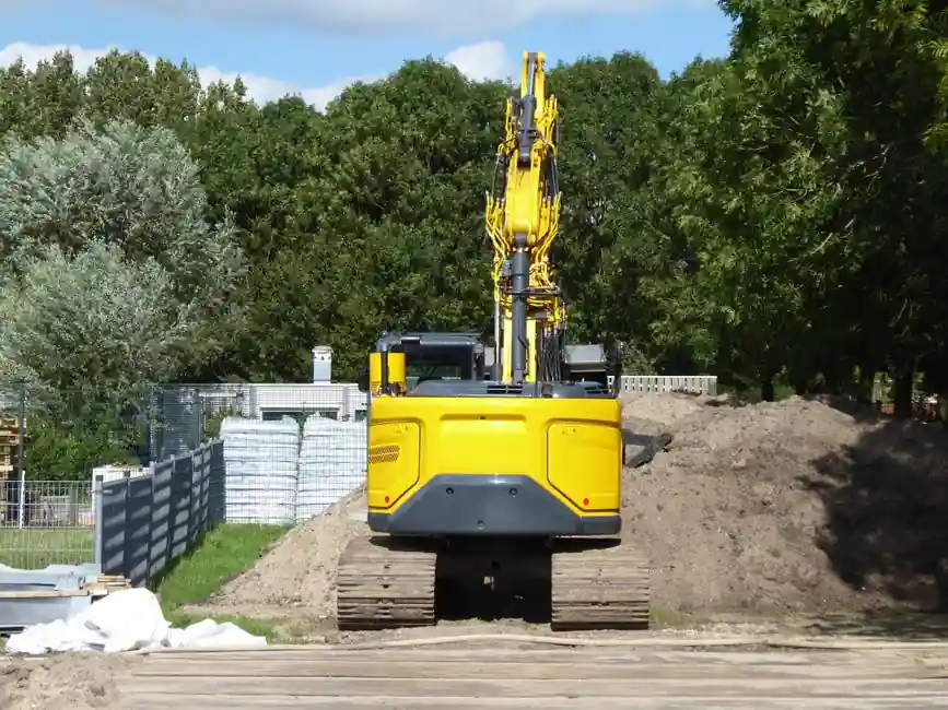
The dynamic compactor crane and drop-height selection determines whether the proposed tamper mass and 15–25 m starting height can actually be delivered repeatedly at the required spacing. Dynamic compaction requires repeated lifting and free fall of a heavy steel tamper, normally 1.5–1.8 m in diameter in published practice [S5].
Check crane capacity against the complete suspended load, including tamper, lifting gear, and rigging, with the required operating radius and drop height. Do not select the largest tamper available; excessive energy can increase vibration, noise, heave, and damage risk without proving better densification [S3][S4].
For construction planning, the broader equipment reference for dynamic compaction can help distinguish the impact method from vibratory or conventional static compaction. This distinction matters because a 6 m fill requires depth treatment, not merely surface rolling to 95% of maximum dry density.
Production sequence and acceptance
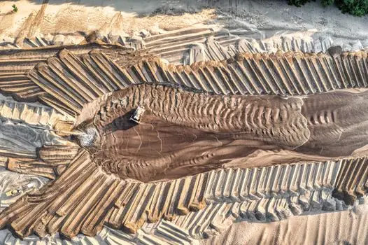
Level and compact craters between energy passes, then apply the next pass on the planned grid [S5]. A practical sequence for the 6 m fill is: trial impacts, select energy and spacing, place and compact fill to the required working level, execute dynamic compaction in passes, level after each pass, and verify the treated zone below 6 m.
Specify acceptance in measurable terms. The contract record should identify tamper mass, drop height, grid spacing, drops per point, number of passes, craters leveled, field test locations, and achieved acceptance values. FHWA/RD-86/133 covers suitability, depth and degree of improvement, drop-point spacing, unit applied energy, monitoring, and offsite vibration prediction; its 10–35 ft improvement range was based on particular natural and fill deposits and should not be treated as a universal performance guarantee [S1].
Finalize the energy level only after the trial demonstrates adequate settlement and subsurface resistance through the full 6 m treatment depth. If the granular fill responds well, remain near the 10–20 t and 15–25 m trial band. If it does not, investigate drainage and stratigraphy before moving to more than 20 t or more than 25 m drop height.